Exposure parameter correcting method and imaging device

A technology of exposure parameters and imaging devices, which is applied to control exposure, optics, image communication, etc., and can solve the problems of general products without suitable structure, unable to obtain correction results, and inconvenience

Active Publication Date: 2012-08-22
ABILITY ENTERPRISE CO LTD
View PDF10 Cites 3 Cited by
  • Summary
  • Abstract
  • Description
  • Claims
  • Application Information

AI Technical Summary

Problems solved by technology

As can be seen from the foregoing, the preset delay time usually does not match the mechanical shutter of the actual imaging device. Therefore, the correction result of the traditional sensitivity will inevitably fail to obtain an accurate correction result
[0005] It can be seen that the above-mentioned existing sensitivity correction method obviously still has inconvenience and defects in structure and use, and needs to be further improved urgently.
In order to solve the above-mentioned problems, the relevant manufacturers have tried their best to find a solution, but for a long time no suitable design has been developed, and the general product has no suitable structure to solve the above-mentioned problems. This is obviously the relevant industry. Urgent problem

Method used

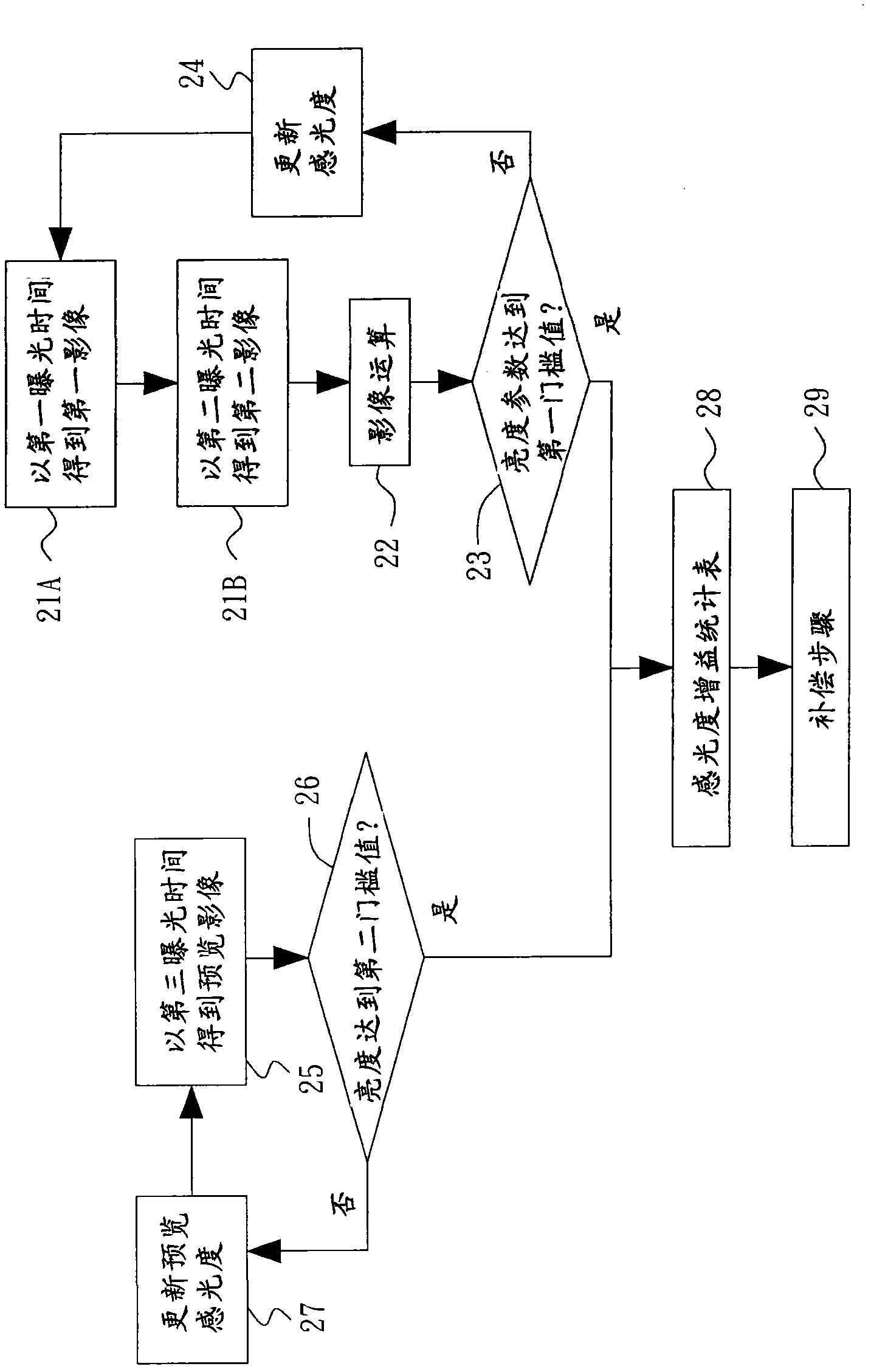
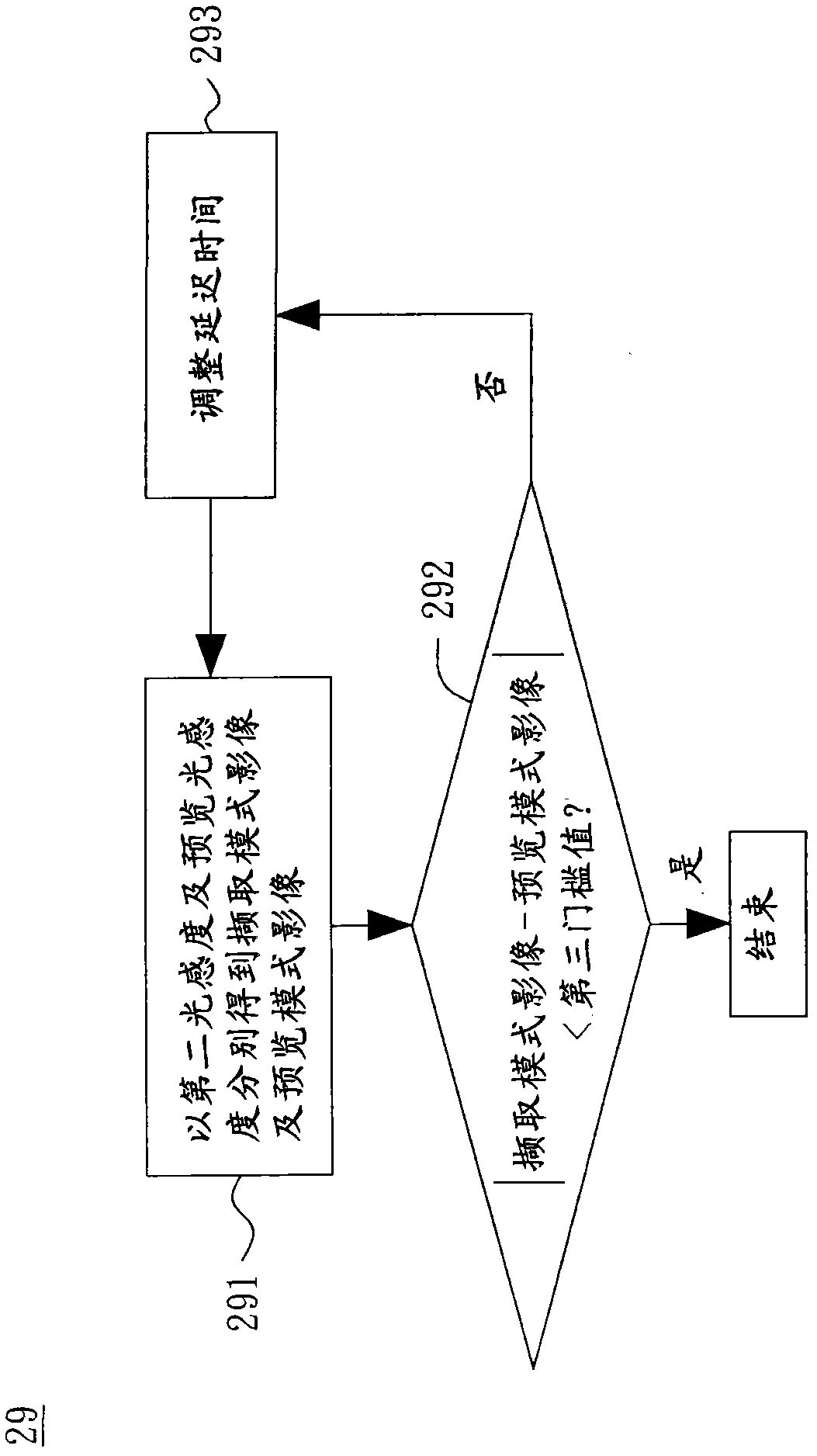

Image

  • Exposure parameter correcting method and imaging device
  • Exposure parameter correcting method and imaging device
  • Exposure parameter correcting method and imaging device

Examples


Embodiment Construction

[0033] In order to further explain the technical means and effects of the present invention to achieve the intended purpose of the invention, the specific implementation, structure and features of the exposure parameter correction method and imaging device proposed according to the present invention will be described below in conjunction with the accompanying drawings and preferred embodiments. And its effect, detailed description is as follows.

[0034] figure 1 A system block diagram of an imaging device according to an embodiment of the present invention is shown. The imaging device can be a camera with image capture function, video camera, mobile phone, personal digital assistant, digital music player, network camera or image capture and testing system, but not limited thereto.

[0035] refer to figure 1, in this embodiment, the imaging device mainly includes an image sensing unit 10 , an electronic shutter 12 , a mechanical shutter 14 , a computing center 16 and a stora...


PUM


Abstract

The invention relates to an exposure parameter correcting method and an imaging device. The exposure parameter correcting method comprises the following steps of: according to a first light sensitivity degree and pre-set time, respectively executing an image capturing step of a capturing mode by first exposure time and second exposure time so as to obtain a first image and a second image; carrying out image calculation on the first image and the second image to obtain a differential image; and replacing the first light sensitivity degree by a second light sensitivity degree and recording the second light sensitivity degree.

Description

technical field [0001] The invention relates to an imaging device, in particular to a method for correcting exposure parameters. Background technique [0002] The image sensing element is an important component of the imaging device, which is used to convert the optical signal into an electrical signal for subsequent processing by the processing unit. However, due to the difference in characteristics of image sensing elements, the sensitivity between the preview mode and the capture mode cannot be maintained in an absolute fixed relationship. Therefore, it is necessary to calibrate the sensitivity of the preview mode and the capture mode separately. [0003] Exposure control in preview mode uses an electronic shutter, while exposure control in capture mode uses a mechanical shutter. The accuracy of the mechanical shutter is lower because it takes a period of time for the mechanical shutter to close until it is completely closed, which is called the lag time of the mechanic...

Claims


Application Information

Patent Timeline
IPC IPC(8): G03B7/08H04N5/235
Inventor 陈泰宏蔡亦雯李宜坚
Owner ABILITY ENTERPRISE CO LTD
Why Eureka
Try Eureka