
Phase microscopic device for transmission type samples and phase microscopic method

A phase microscopy and transmission type technology, which is used in microscopes, phase influence characteristics measurement, instruments, etc., can solve the problems of inability to distinguish the convolution combination of the object itself and other functions, difficult to obtain reconstructed images, and limited application scope.

Active Publication Date: 2012-08-22
SHANGHAI INST OF OPTICS & FINE MECHANICS CHINESE ACAD OF SCI
View PDF2 Cites 24 Cited by
  • Summary
  • Abstract
  • Description
  • Claims
  • Application Information

AI Technical Summary

Problems solved by technology

[0011] The CDI algorithm has a simple structure and can theoretically reach the resolution of the diffraction limit, but this imaging method requires the sample to be an isolated object, and theoretically it cannot distinguish the object itself from its conjugate and the convolution of itself and other functions combination, it is often difficult to obtain an ideal reconstructed image for slightly complex objects, which greatly limits its application range

Method used


Image

  • Phase microscopic device for transmission type samples and phase microscopic method
  • Phase microscopic device for transmission type samples and phase microscopic method
  • Phase microscopic device for transmission type samples and phase microscopic method

Examples


Embodiment Construction

[0044] The present invention will be further described below in conjunction with the embodiments and drawings, but the protection scope of the present invention should not be limited by this.

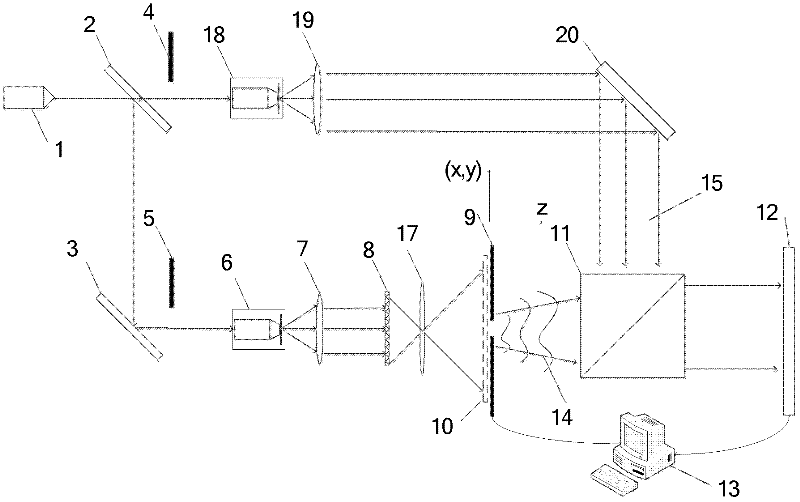
[0045] See first figure 1 , figure 1 It is the optical path diagram of the transmission type phase microscope imaging device using the coaxial interference optical path in the present invention. It can be seen from the figure that the transmission type sample phase microscope device of the present invention consists of a coherent light source 1, a beam splitter 2, a first mirror 3, a first baffle 4, a second baffle 5, a first spatial filter 6, and a first lens. 7. The sample to be tested 8, a small aperture diaphragm 9, a real image 10, a prism 11, a detector 12, a computer 13, an imaging lens group 17, a second spatial filter 18, a second lens 19 and a second mirror 20, The positional relationship of the above components is as follows:

[0046] The light emitted by the coherent light sou...


PUM


Abstract

The invention discloses a phase microscopic device for transmission type samples and a phase microscopic method. Based on a coaxial holographic light path, an amplified real image of a transmission type object, after being scanned by using a small hole, is taken as object light, scattering spots are formed on a target surface of a detector at a distance and interfered with plane waves in the same direction, the light intensity distributions formed when the scattering spots exist separately and the scattering spots are interfered with reference light are respectively recorded when the small hole is located at different positions, meanwhile, a situation that the reference light is not changed is ensured, and the light intensity distribution of the reference light is recorded once. A reproductive image (including amplitude and phase) with a size far larger than the size of the target surface of the detector is obtained in a mode of carrying out an iterative operation by using a computer. A reproductive image produced in the invention not only has the interference of zero-order images and conjugate images, but also can carry out phase microscopic imaging on a transmission type sample with a size far larger than the size of the target surface of the detector because a mode of small-hole scanning and prevention is adopted; and because of the introduction of the reference light, compared with a common iterative algorithm, the convergence speed is faster.

Description

Technical field [0001] The invention relates to imaging and phase measurement of a transmission type sample, in particular to a transmission type sample phase microscopy device and a phase microscopy method. Background technique [0002] Since the image obtained by a microscope is often a combination of a clear focused image and other defocused images, in order to maximize the resolving power of the microscope, the sample needs to be made into very thin sections, but as the sample becomes thinner, light is transmitted At the same time, the contrast of the image observed by the ordinary microscope will be reduced. When the sample is thin to a certain extent, the entire field of view will be basically uniform, and it is difficult to observe the detailed structure of the object. Zernike phase contrast microscope solves the problem of observing phase objects and promotes the progress of related science to a large extent. Although phase-contrast microscopes solve the problem of obser...

Claims


Application Information

Patent Timeline
IPC IPC(8): G02B21/26G02B21/18G02B21/00G01N21/41
Inventor 潘兴臣刘诚朱健强
Owner SHANGHAI INST OF OPTICS & FINE MECHANICS CHINESE ACAD OF SCI
Learn More