
Resonant system

A resonant system and resonant cavity technology, applied in the field of resonant systems, can solve the problems of limited shell structure layout, inability to weaken noise, etc., and achieve the effect of simple processing and convenient installation

Active Publication Date: 2012-08-22
MANN HUMMEL GMBH
View PDF9 Cites 19 Cited by
  • Summary
  • Abstract
  • Description
  • Claims
  • Application Information

AI Technical Summary

Problems solved by technology

However, these resonators are either single-cavity resonators that cannot effectively attenuate noise at different frequencies, or their shell structure layout limits the layout of the internal resonant cavity.

Method used


Image

  • Resonant system
  • Resonant system
  • Resonant system

Examples


Embodiment Construction

[0066] It is easy to understand that, according to the technical solutions of the present invention, those skilled in the art can propose multiple structural modes of the present invention without changing the essence and spirit of the present invention. Therefore, the following specific embodiments and drawings are only specific descriptions of the technical solution of the present invention, and should not be regarded as the entirety of the present invention or as a limitation or restriction on the technical solution of the present invention.

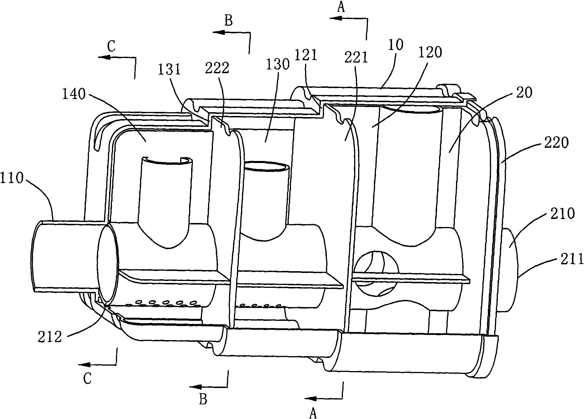
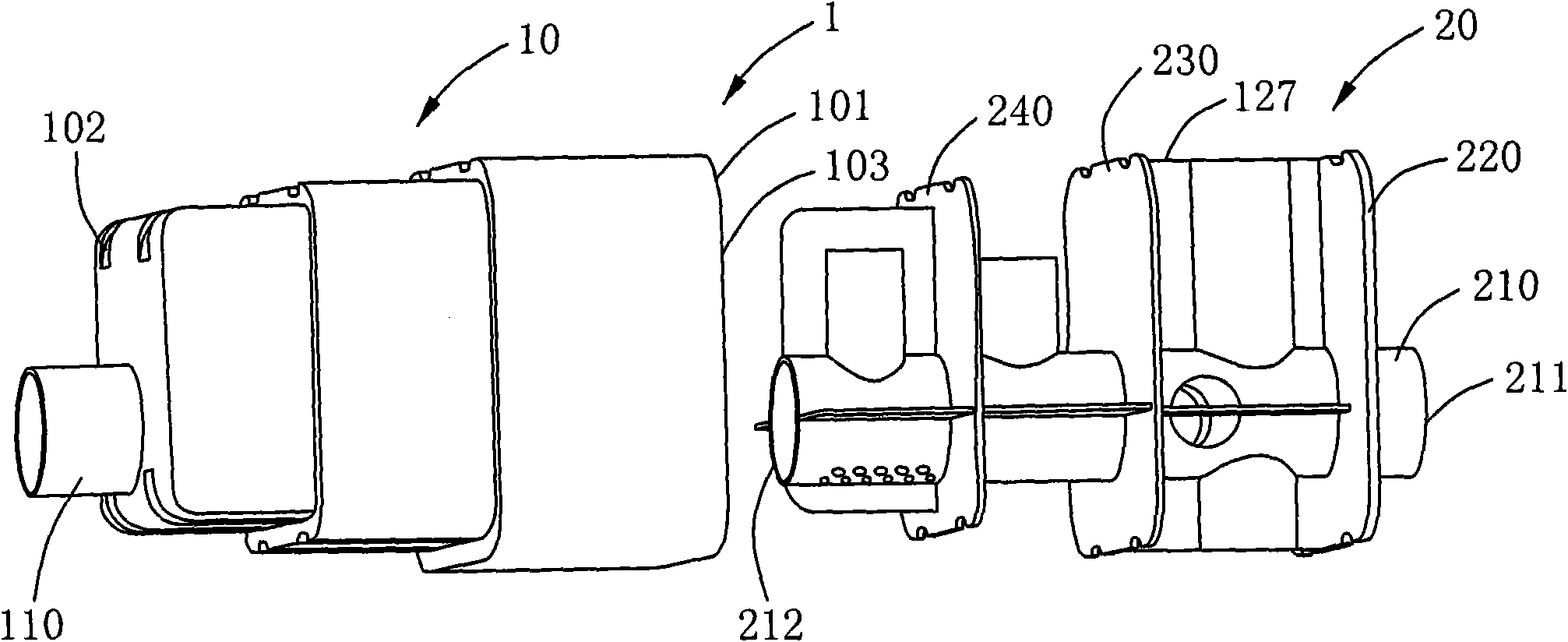
[0067] In addition, if the terms "upstream" and "downstream" are used in the present invention, they indicate the direction of being "upstream" or "downstream" of the flowing gas along the direction of gas inflow in the intake system. This is obvious to those skilled in the art. The directions of "Up", "Down", "Left", and "Right" are all based on the attached figure 1 and 2 orientation shown in .

[0068] Below with reference to th...


PUM


Abstract

The invention relates to a resonant system. The invention relates to a device for a gas inlet system, wherein the device comprises a shell and a plugged connection part; the shell is provided with a structure the interior of which is a cavity; an opening is arranged at a first end part of the shell; the plugged connection part can be inserted into the cavity of the shell through the opening in a shape matched manner; the shell is provided with a first gas guide pipe; the plugged connection part comprises a second gas guide pipe; the second gas guide pipe is provided with the first end part and a second end part; a first lateral plate is close to a first end part of the second gas guide pipe; and the opening can be hermetically covered by the first lateral plate; furthermore, the first gas guide pipe or a gas guide hole and the second gas guide pipe commonly form a gas inlet pipeline through which gas can flow in or out. The resonant system disclosed by the invention has the advantages of being convenient for processing and simple for assembly.

Description

【Technical field】 [0001] The invention relates to a vehicle noise reduction device, in particular, the invention relates to a resonance system used in a vehicle air intake system to reduce engine intake noise. 【Background technique】 [0002] At present, vehicles are more and more commonly integrated into the lives of ordinary families. People are also paying more and more attention to the noise and vibration quality (NVH) of the vehicle. Intake system noise is one of the main sources of noise inside the car. The engine intake system mainly includes an air filter and an intake manifold, where the air filter is mainly used to filter the air entering the engine to remove impurities in the air. [0003] The intake noise of a naturally aspirated engine is formed by pressure fluctuations caused by the periodic opening and closing of the intake valve. It mainly includes the intake pulsation noise caused by the variable speed movement of the piston when the intake valve is opened...

Claims


Application Information

Patent Timeline
IPC IPC(8): F02M35/12F02M35/02F02M35/14
CPCF02M35/1261F02M35/1266F02M35/14
Inventor 贾维新沈晶
Owner MANN HUMMEL GMBH
Learn More