
Two-stroke opposed-piston diesel engine

A diesel engine and opposed piston technology, which is applied to engine components, machines/engines, mechanical equipment, etc., can solve the problems of low energy conversion efficiency, long manufacturing cycle, and high maintenance cost, and achieve high energy conversion efficiency and low manufacturing replacement costs Low, wide range of effects

Inactive Publication Date: 2012-08-22
李玉龙
View PDF0 Cites 19 Cited by
  • Summary
  • Abstract
  • Description
  • Claims
  • Application Information

AI Technical Summary

Problems solved by technology

During the working process of the traditional piston engine, part of the energy generated by the explosion of the combustible mixture in the combustion chamber is converted into heat energy and absorbed by the elastic deformation of the engine cylinder head. The energy generated by the explosion cannot be fully utilized for effective work and output power, and the energy conversion efficiency is low. (only 25-35%); limited by the structure of the traditional piston engine, the intake air volume of a single cylinder is small, the fuel combustion is insufficient, the fuel consumption is large, and the exhaust pollution is serious; because the traditional piston engine needs complex valve mechanism to cooperate to be normal Work, complex structure, high failure rate, high maintenance requirements, high maintenance costs; traditional piston engine cylinder head, cooling system, lubrication system layout is not flexible, the engine is large, heavy, and installation layout is not flexible; engine block structure Complex, difficult to process, high manufacturing cost, long production cycle, high engine manufacturing cost
To sum up, the traditional piston engine has low energy conversion efficiency, high fuel consumption, high exhaust pollution, complex structure, high failure rate, large volume, low horsepower per unit mass, high manufacturing cost, long manufacturing cycle, and difficult maintenance. Disadvantages such as high cost of use and inflexible installation and layout do not meet the requirements of the development trend of energy conservation and environmental protection in the whole society

Method used


Image

  • Two-stroke opposed-piston diesel engine
  • Two-stroke opposed-piston diesel engine
  • Two-stroke opposed-piston diesel engine

Examples


Embodiment Construction

[0026] Further details are given below in accordance with the accompanying drawings:

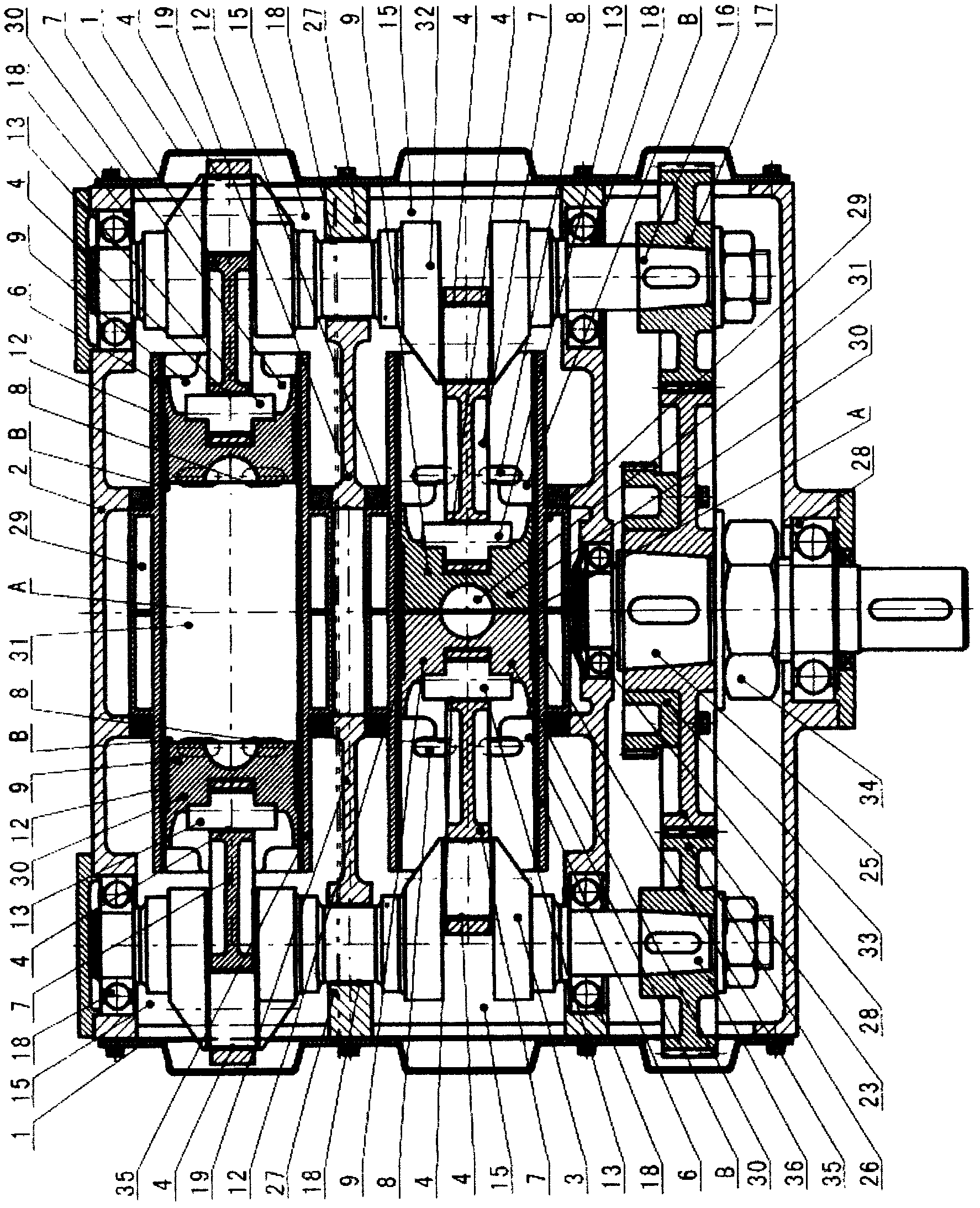
[0027] Such as figure 1 , image 3As shown, the cylinder block 2 is the installation base and supporting framework of the two-stroke opposed-piston diesel engine. The cooling water jacket 29 is integrated inside the cylinder barrel 6 to cool the cylinder barrel 6, the piston mechanism 30, the fuel nozzle 10, the exhaust valve 22 and the like. The cylinder barrel 6 fixed on the horizontal plane can be divided into two parts with the same structure on the left and right from the center. The notch 5 is arranged at the two ends of the cylinder barrel 6 corresponding to the big end of the connecting rod 7. The function of the notch 5 is to avoid when the connecting rod 7 moves. The movement space of the connecting rod 7 large ends reduces the width of the engine and the length and quality of the moving parts, and reduces the self-load of the engine. Air inlets 8 of varying numbers are arranged...


PUM


Abstract

The invention relates to a two-stroke opposed-piston diesel engine. The existing piston-type engine structure is that a piston is arranged inside an engine cylinder, the piston is connected with a crankshaft through a connecting rod to form a crankshaft linkage mechanism, and the energy conversion efficiency is only 25 to 35 percent. The invention aims at designing a two-stroke opposed-piston diesel engine. The two-stroke opposed-piston diesel engine structurally consists of piston mechanisms (3), a power output mechanism (34), a left crankshaft linkage mechanism (36), and a right crankshaft linkage mechanism (32), wherein the piston mechanisms (3) with the same structure and capable of synchronously moving in opposite directions are oppositely arranged at two sides inside an air cylinder barrel (6) of an air cylinder body (2), a burning chamber (31), a fuel oil nozzle mechanism (10) and a vent valve mechanism (22) are arranged on the middle position of the cylinder barrel (6). The two-stroke opposed-piston diesel engine has the advantages that by adopting a unique structure, two pistons are ingeniously and symmetrically arranged inside the cylinder barrel, so that multiple problems existing in the traditional piston-type engine can be high efficiently and reliably solved. The energy conversion efficiency can be improved.

Description

[0001] 1. The fields mentioned [0002] The invention relates to a structure of an opposed-piston diesel engine, in particular to a two-stroke opposed-piston diesel engine. 2. Background technology [0003] The structure and principle of present piston engine are: a set of piston mechanism is placed in engine cylinder barrel, and piston is connected with a crankshaft by connecting rod, forms crank-link mechanism. The upper plane of the piston, the inner wall of the cylinder bore and the inner surface of the engine cylinder head together form the combustion chamber. The combustible mixture explodes in the combustion chamber to generate energy, which pushes the piston to move downward along the cylinder, drives the crankshaft to rotate in a circle through the crank-link mechanism, and outputs power from the crankshaft. Under the action of the inertia of the last working stroke, the crank-link mechanism continuously completes the intake-compression-work-exhaust process successiv...

Claims


Application Information

Patent Timeline
IPC IPC(8): F02B75/28F02B75/02F02B75/18F02F1/22
Inventor 李玉龙李少波王应江王性劳宋稳联
Owner 李玉龙
Learn More