Self-locking and lever principle-based vehicle electrical control/manual double-purpose safety hammer
A lever principle, safety hammer technology, applied in the direction of vehicle safety arrangement, pedestrian/occupant safety arrangement, vehicle components, etc., can solve the problem of safety hammer lost passengers, etc., and achieve the effect of improving reliability, simple assembly structure, and convenient escape.
- Summary
- Abstract
- Description
- Claims
- Application Information
AI Technical Summary
Problems solved by technology
Method used
Image
Examples
Embodiment 1
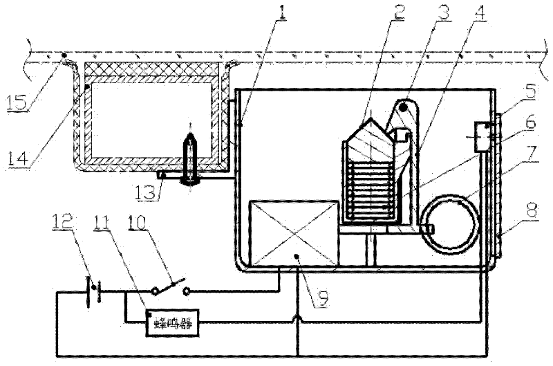
[0017] figure 1 It is a structural schematic diagram of the first embodiment of the present invention. The housing 1 is a box body that integrates the circular guide cavity, the mounting bracket of the self-locking force component device 4 and the fixed base of the electromagnet 9, and is fixed on the side window frame 14 of the vehicle body with the fixing bracket 13, and the fixing bracket 13 It is L-shaped; the hammer head 2 adopts a tapered hammer head, and the bottom plane is in contact with the compression spring 6, and is installed in the circular guide cavity of the housing 1; the self-locking force component device 4 is an L-shaped lever, which is installed through the pin shaft 3 On the mounting bracket of the housing 1, the short arm end is in contact with the cone surface of the hammer head 2, and the long arm end is in contact with the iron core of the electromagnet 9; the pull ring 7 is installed at the lower end of the self-locking force component device 4, and ...
Embodiment 2
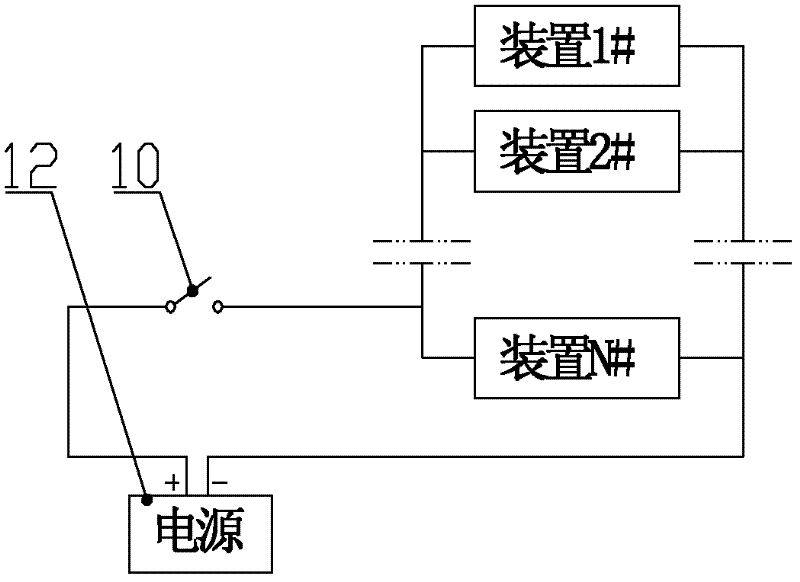
[0021] figure 2 It is a structural schematic diagram of the second embodiment of the present invention. The housing 1 is a box that integrates the circular guide cavity and the mounting bracket of the self-locking force component device 4. It is fixed on the side window frame 14 of the vehicle body with a fixed bracket 13, and the fixed bracket 13 is L-shaped; the hammer head 2 Tapered hammer head is used, the bottom plane is in contact with the compression spring 6, and installed in the circular guide cavity of the housing 1; the self-locking force component 4 is an L-shaped lever, which is installed on the mounting bracket of the housing 1 through the pin shaft 3 On the top, the short arm end is in contact with the cone surface of the hammer head 2; the pull ring 7 is installed at the lower end of the self-locking force component device 4 and connected with the long arm end of the self-locking force component device 4; the safety cover 8 is installed on the right side of th...
PUM
 Abstract
Description
Claims
Application Information
 - R&D
- Intellectual Property
- Life Sciences
- Materials
- Tech Scout
- Unparalleled Data Quality
- Higher Quality Content
- 60% Fewer Hallucinations
Browse by: Latest US Patents, China's latest patents, Technical Efficacy Thesaurus, Application Domain, Technology Topic, Popular Technical Reports.
© 2025 PatSnap. All rights reserved.Legal|Privacy policy|Modern Slavery Act Transparency Statement|Sitemap|About US| Contact US: help@patsnap.com


