
Video encoding and decoding interframe image predicting method and video codec

A prediction method and video coding technology, applied in image communication, digital video signal modification, television, etc., can solve the problems of low video coding and decoding efficiency and failure to use

Inactive Publication Date: 2012-08-15
LG ELECTRONICS (CHINA) R&D CENT CO LTD
View PDF4 Cites 12 Cited by
  • Summary
  • Abstract
  • Description
  • Claims
  • Application Information

AI Technical Summary

Problems solved by technology

However, the image signal after interpolation is used to predict the current frame, and the image information of the current frame cannot be utilized in the existing interpolation algorithm
[0004] In the proposals of international video compression coding standards in the past two years, among the improved algorithms for inter-frame image coding and decoding prediction information, there is a second-order prediction of inter-frame image prediction information by using the spatial adjacent information of the current coded / decoded block in the current frame. However, in the process of realizing the present invention, the inventor found that all these algorithms are changes to the inter-frame prediction information, and the efficiency of video encoding and decoding is not high

Method used


Image

  • Video encoding and decoding interframe image predicting method and video codec
  • Video encoding and decoding interframe image predicting method and video codec
  • Video encoding and decoding interframe image predicting method and video codec

Examples


specific example

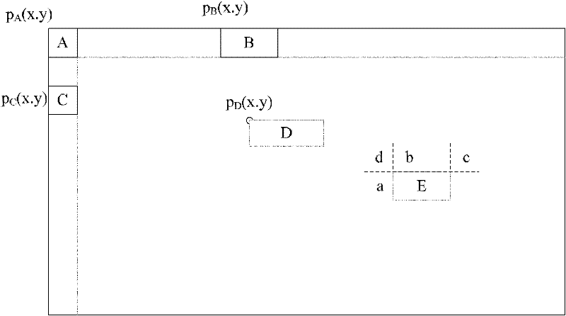
[0074] Take setting the interpolation flag in the PU as an example, the PU located at the left and upper border of the image, for example image 3 PU A, B and C in. In this case, combo_interpolation_flag is encoded in the syntax, that is, the current PU is set with combo_interpolation_flag in the current frame. When the PU is not at the left and upper borders of the image, for example image 3 In the PU E, whether the combo_interpolation_flag syntax is encoded depends on the value of the combo_interpolation_flag of its adjacent PUs, specifically divided into the following two cases.

[0075] When the combo_interpolation_flag of three adjacent PUs has the same value, the combo_interpolation_flag of the current PU is not encoded in the syntax element, that is, the combo_interpolation_flag is not set in the current prediction unit in the current frame, but can be calculated from the combo_interpolation_flag of the adjacent PU, and its value It is the combo_interpolation_...


PUM


Abstract

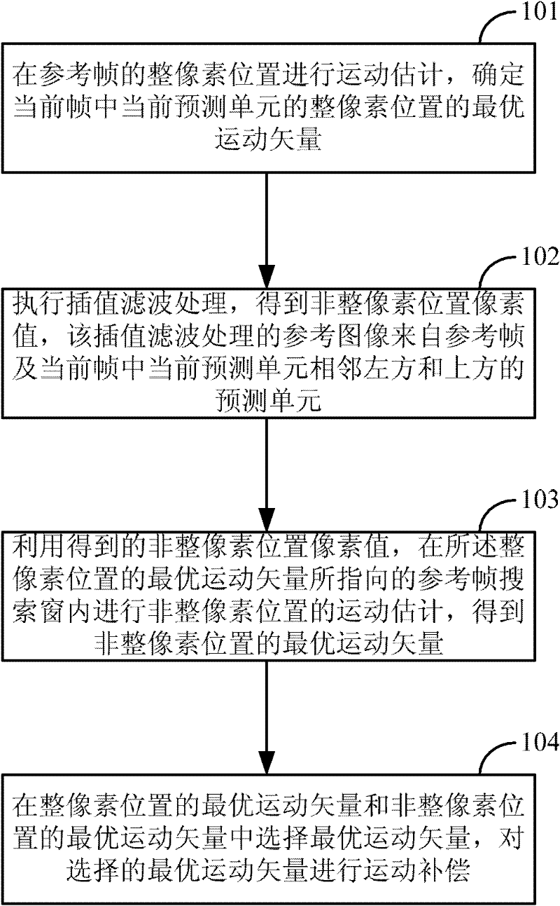
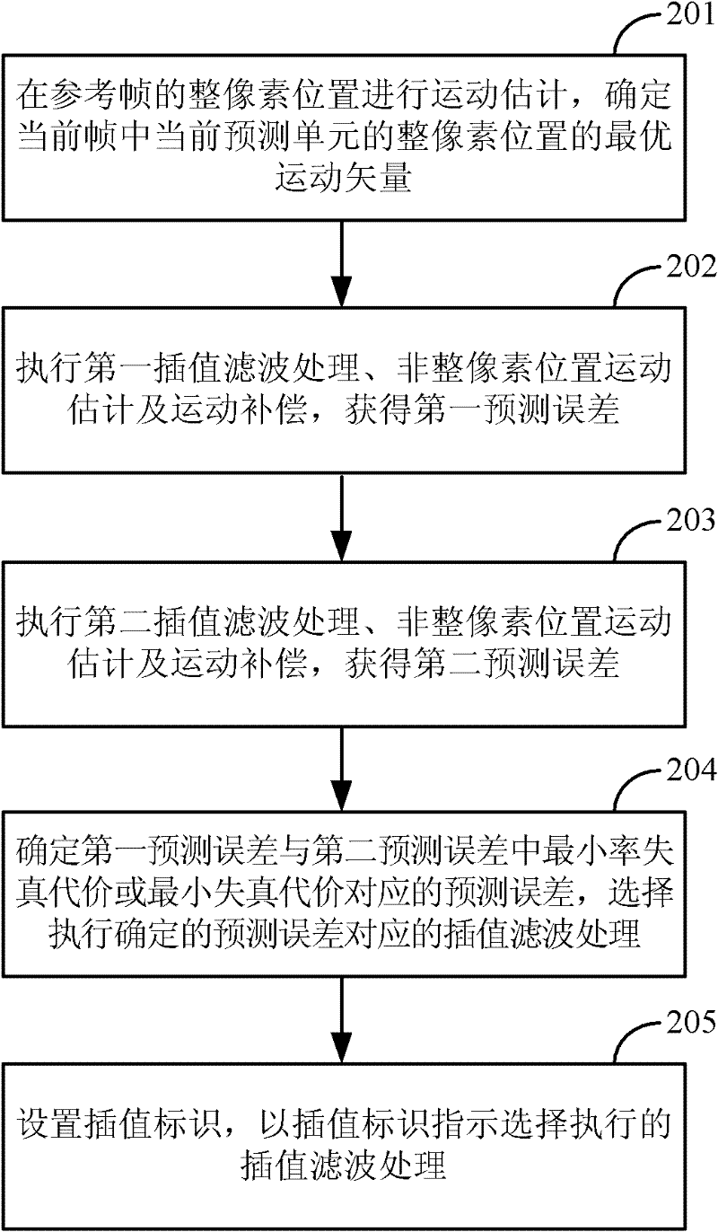
The invention discloses a video encoding and decoding interframe image predicting method and a video codec. The method comprises the following steps: conducting motion evaluation at a position of the whole pixel of a reference frame, and determining the optimum motion vector of the whole pixel position of the current predicting unit in the current frame; then respectively executing first interpolation filter process, non-whole pixel position motion evaluation and motion compensation to obtain a first prediction error, executing second interpolation filter process, non-whole pixel position motion evaluation and motion compensation to obtain a second prediction error, wherein the reference image of the first interpolation filter process comes from prediction units adjacent to the left and upper side of the current predicting unit in the current frame, and the reference image of the second interpolation filter process comes from the reference frame; selecting to execute interpolation filter process corresponding to prediction errors with minimum rate distortion cost or minimum distortion cost in the first prediction error and the second prediction error; and setting interpolation identification so as to lead the interpolation identification to indicate the execution of the selected interpolation filter process. With the invention, the video coding and decoding efficiency can be improved.

Description

technical field [0001] The invention relates to the technical field of moving image predictive coding and interpolation filtering, in particular to a video codec inter-frame image prediction method and a video codec. Background technique [0002] Motion image compression coding and decoding are generally divided into two predictive coding and decoding technologies: inter-frame image coding and intra-frame image coding and decoding. Intra-frame image encoding / decoding uses information from already encoded / decoded image blocks of the current frame to perform predictive encoding / decoding on the currently encoded / decoded image block. Inter-frame image encoding / decoding performs predictive encoding / decoding on the currently encoded / decoded image by using the image frame information that has been encoded / decoded. [0003] Inter-frame image encoding / decoding provides inter-frame image prediction with the smallest possible residual signal for the current frame by interpolating and ...

Claims


Application Information

Patent Timeline
IPC IPC(8): H04N7/26H04N7/46H04N19/51H04N19/57H04N19/80
Inventor 贾杰
Owner LG ELECTRONICS (CHINA) R&D CENT CO LTD
Learn More