Printing template
A technology of templates and printing media, applied in printing devices, printing, typewriters, etc., can solve the problems of troublesome assembly of components, fracture of elastic bodies, cumbersome operation, etc., and achieve the effect of simple structure and easy installation and operation
- Summary
- Abstract
- Description
- Claims
- Application Information
AI Technical Summary
Problems solved by technology
Method used
Image
Examples
no. 1 example
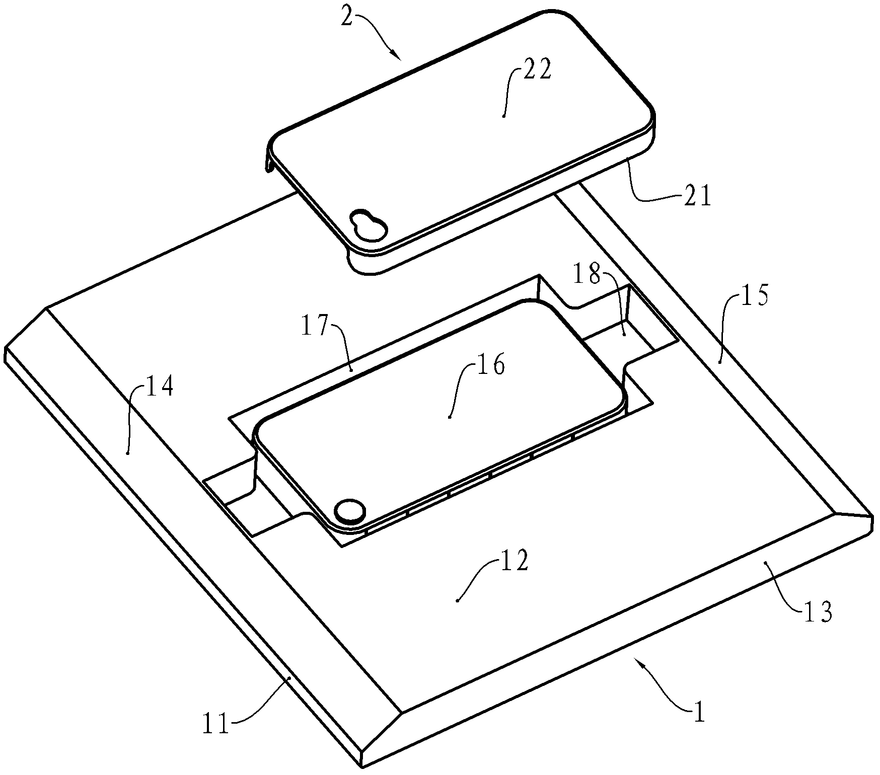
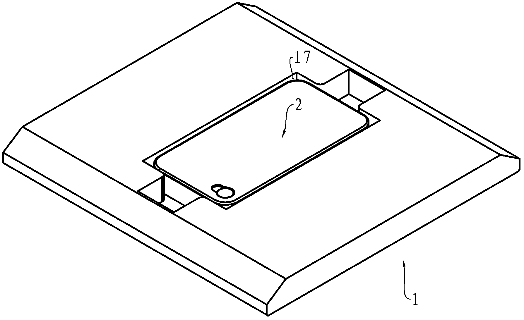
[0022] see figure 1 , the body of the printing template 1 has a front side 11, a rear side, an upper surface 12, a lower surface, a left side 13 and a right side, as well as a supporting surface 16 for supporting the printing medium 2 in the direction of gravity. This example is a For the example of carrying out pattern printing to the mobile phone back cover, the printing medium 2 is a mobile phone back cover, and the support surface 16 can only be used for the support surface of the mobile phone back cover panel 22, and can also only be used to support the mobile phone back cover 2 skirts The supporting surface of the lower surface 21 of the plate can also be a combination of the two. The upper surface 12 is provided with a groove 17 that is concave downward and adapted to the skirt of the back cover of the mobile phone. The two sides of the groove 17 constitute the positioning part. In addition, notches 18 are respectively provided on the front and back of the upper surfac...
no. 2 example
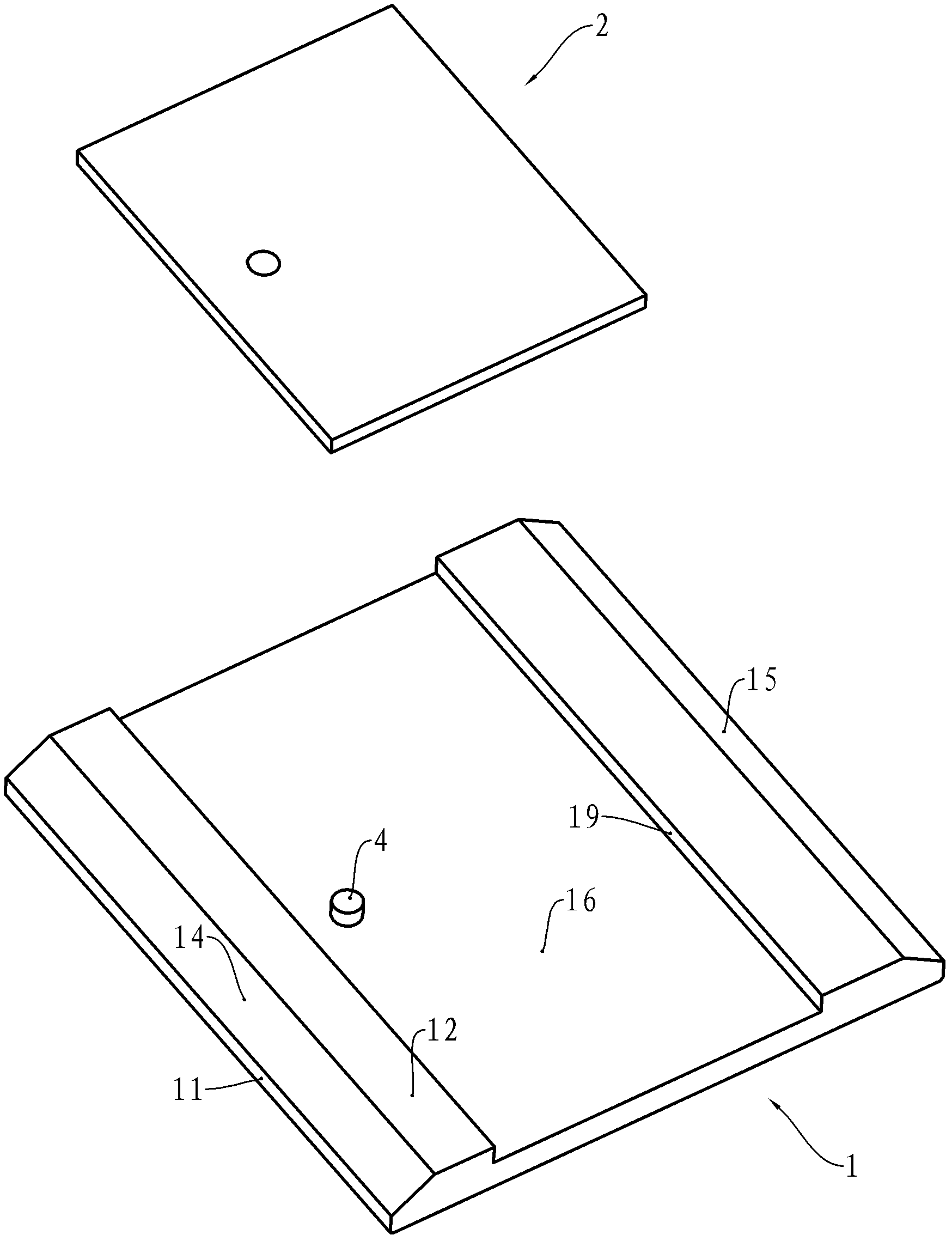
[0026] see image 3 , for the printing medium 2 is a relatively thin tile sheet, plastic board, etc., the printing template 1 can have the following changes compared with the first embodiment, and only the differences will be specifically described below. The printing medium 2 applicable in this example is a hard photo board that can be hung on the wall, and there is a nail hole for hanging on the board. The supporting surface 16 of the printing template 1 is located below the upper surface 12 in parallel. Considering that the printing template 1 should be suitable for hard photo plates of different formats, under the premise of meeting the maximum printing format of the flatbed printer, the supporting surface 16 should be as large as possible. The positioning of the printing medium 2 on the support surface is completed by the positioning surface 19 and the positioning pin 4. It can be understood that the adaptation of the positioning pin 4 to the hard photo boards of differen...
no. 3 example
[0028] see Figure 4 , the difference between this embodiment and the second embodiment is that one of the front bevel 14 or the rear bevel 15 is canceled, this is because the printing medium 2 is thinner, so that the distance between the upper surface 12 and the lower surface of the printing template is smaller, The maximum stroke of the elastic body in the flatbed printer is also very small, and no noise that affects the environment will be generated, nor will it cause damage to the elastic body. Therefore, the number of inclined surfaces can be appropriately reduced. In addition, the cooperation between the positioning surface 19 and the positioning pin 4 is limited to the outer edge of the outline of the printing medium 2 in this example.
PUM
 Abstract
Description
Claims
Application Information
 - Generate Ideas
- Intellectual Property
- Life Sciences
- Materials
- Tech Scout
- Unparalleled Data Quality
- Higher Quality Content
- 60% Fewer Hallucinations
Browse by: Latest US Patents, China's latest patents, Technical Efficacy Thesaurus, Application Domain, Technology Topic, Popular Technical Reports.
© 2025 PatSnap. All rights reserved.Legal|Privacy policy|Modern Slavery Act Transparency Statement|Sitemap|About US| Contact US: help@patsnap.com


