
Electric tool

A technology for power tools and casings, which is applied in the field of power tools, can solve the problems of increasing the circumferential size of the holding part, not conforming to ergonomics, and uncomfortable holding, etc. Comfortable grip

Inactive Publication Date: 2012-08-15
NANJING CHERVON IND
View PDF7 Cites 2 Cited by
  • Summary
  • Abstract
  • Description
  • Claims
  • Application Information

AI Technical Summary

Problems solved by technology

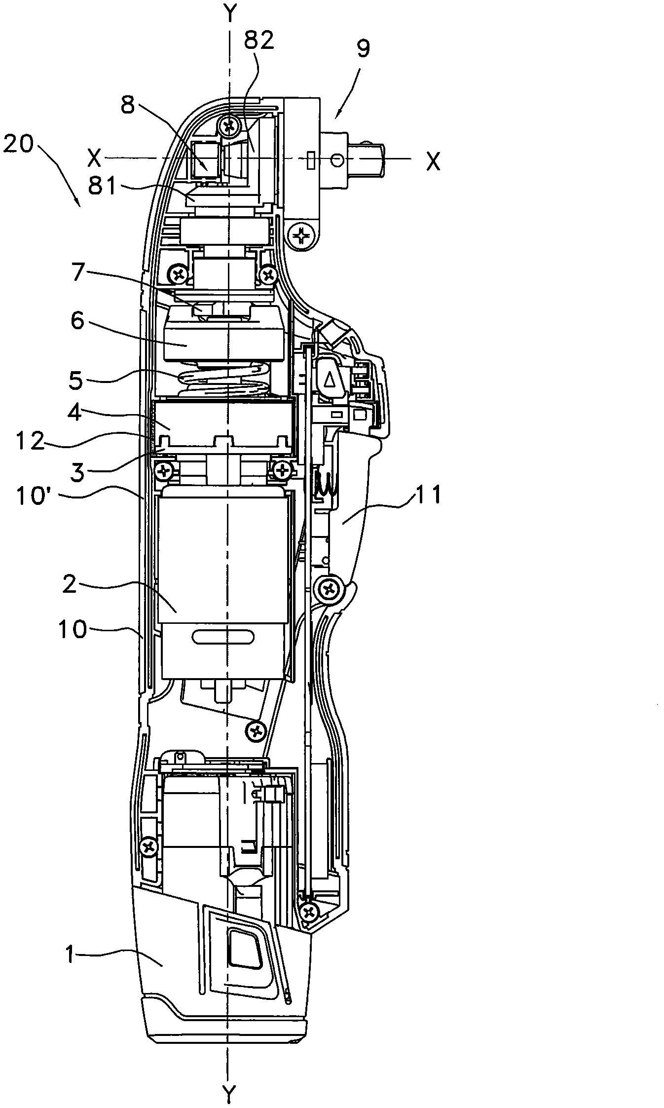
[0002] In the field of electric tools, especially impact wrenches and impact drills with impact function, the gear reduction mechanism is usually housed in the gearbox, especially for the planetary reduction mechanism, there is no gear box housing. However, since the gearbox housing occupies a certain volume in the casing, especially if the gearbox casing is separated from the ring gear, the diameter of this place will become larger. For those gearbox reduction mechanisms that are just located in the fuselage When the grip part is fixed, it will inevitably increase the circumferential dimension of the grip part, which will cause discomfort to the operator during operation, which does not conform to ergonomics; moreover, if there is noise when the gear box reduction mechanism is running at high speed and impact sound, it is difficult to improve without changing the gear parameters and assembly method

Method used


Image

  • Electric tool
  • Electric tool
  • Electric tool

Examples


Embodiment Construction

[0022] The specific implementation manners of the present invention will be further described in detail below in conjunction with the accompanying drawings.

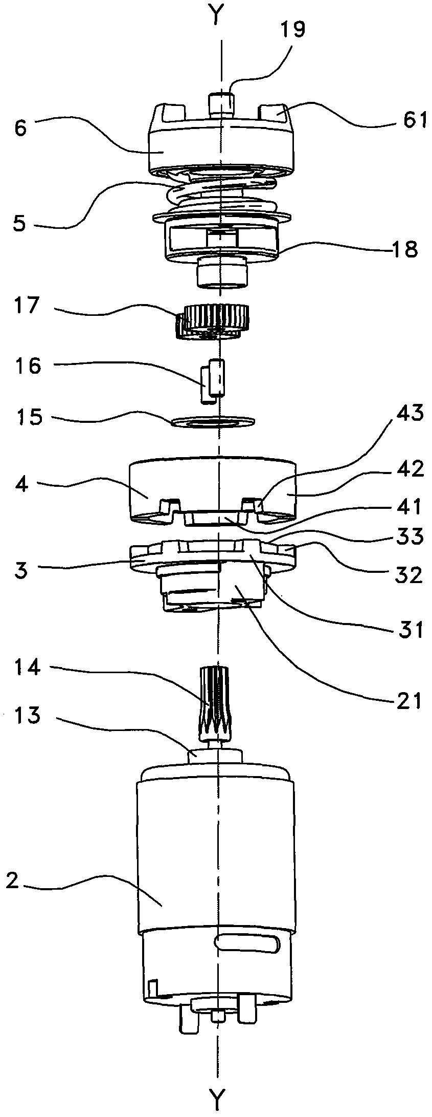
[0023] like figure 1 As shown, the electric tool of the present invention is preferably an angular impact tool 20, which can be an angular impact screwdriver, an angular impact drill or an impact wrench, etc., which is formed by combining two halves of the casing 10. The main body part of 10 is formed with an elongated holding part 10' on the longitudinal axis Y for the operator to hold, and a start switch 11 is installed on the casing 10 at the holding part 10' for controlling The start and stop of the motor 2 in the casing 10, in this embodiment, the motor 2 is powered by the battery pack 1, in other embodiments, the motor 2 can also be powered by an AC, and the front end of the casing 10 is supported by a screwdriver that can be clamped , a working head 9 such as a drill bit, the longitudinal axis X of the working he...


PUM


Abstract

The invention provides an electric tool. The electric tool comprises a shell, a motor placed in the shell and a planet speed reducing mechanism, wherein the planet speed reducing mechanism is provided with a center wheel, a planetary wheel, a planet carrier and a gear ring; and the planet speed reducing mechanism is provided with a gearbox shell in a gapless manner so as to be directly placed in the enclosure. The electric tool can be used for remarkably reducing the radial dimension of a holding part and strengthening the holding comfort feeling of a manipulator, and better accords with man-machine engineering; the traditional gear case shell is omitted, the cost of a part is saved, the structure is simplified, the assembly is convenient, and the production efficiency is improved; and the size and weight of a complete machine are reduced, and the electric tool is more beneficial to operation and carry.

Description

technical field [0001] The invention relates to an electric tool, in particular to a speed reduction mechanism of the electric tool. Background technique [0002] In the field of electric tools, especially impact wrenches and impact drills with impact function, the gear reduction mechanism is usually housed in the gearbox, especially for the planetary reduction mechanism, there is no gear box housing. However, since the gearbox housing occupies a certain volume in the casing, especially if the gearbox casing is separated from the ring gear, the diameter of this place will become larger. For those gearbox reduction mechanisms that are just located in the fuselage When the grip part is fixed, it will inevitably increase the circumferential dimension of the grip part, which will cause discomfort to the operator during operation, which does not conform to ergonomics; moreover, if there is noise when the gear box reduction mechanism is running at high speed When it comes to impa...

Claims


Application Information

Patent Timeline
IPC IPC(8): B25F5/00B25B21/02B25D11/06B25D17/11
Inventor 王小勇赵祥
Owner NANJING CHERVON IND
Learn More