Method and device for tracing maximum power point and power supply system
A technology of maximum power point and power supply system, applied in photovoltaic power generation, electrical components, light radiation generators, etc., can solve problems such as long adjustment time, low response speed, and difficulty in maximum power output, so as to reduce the number of measurements and adjustments The effect of increasing the number of times and improving the overall response speed
- Summary
- Abstract
- Description
- Claims
- Application Information
AI Technical Summary
Problems solved by technology
Method used
Image
Examples
no. 1 example
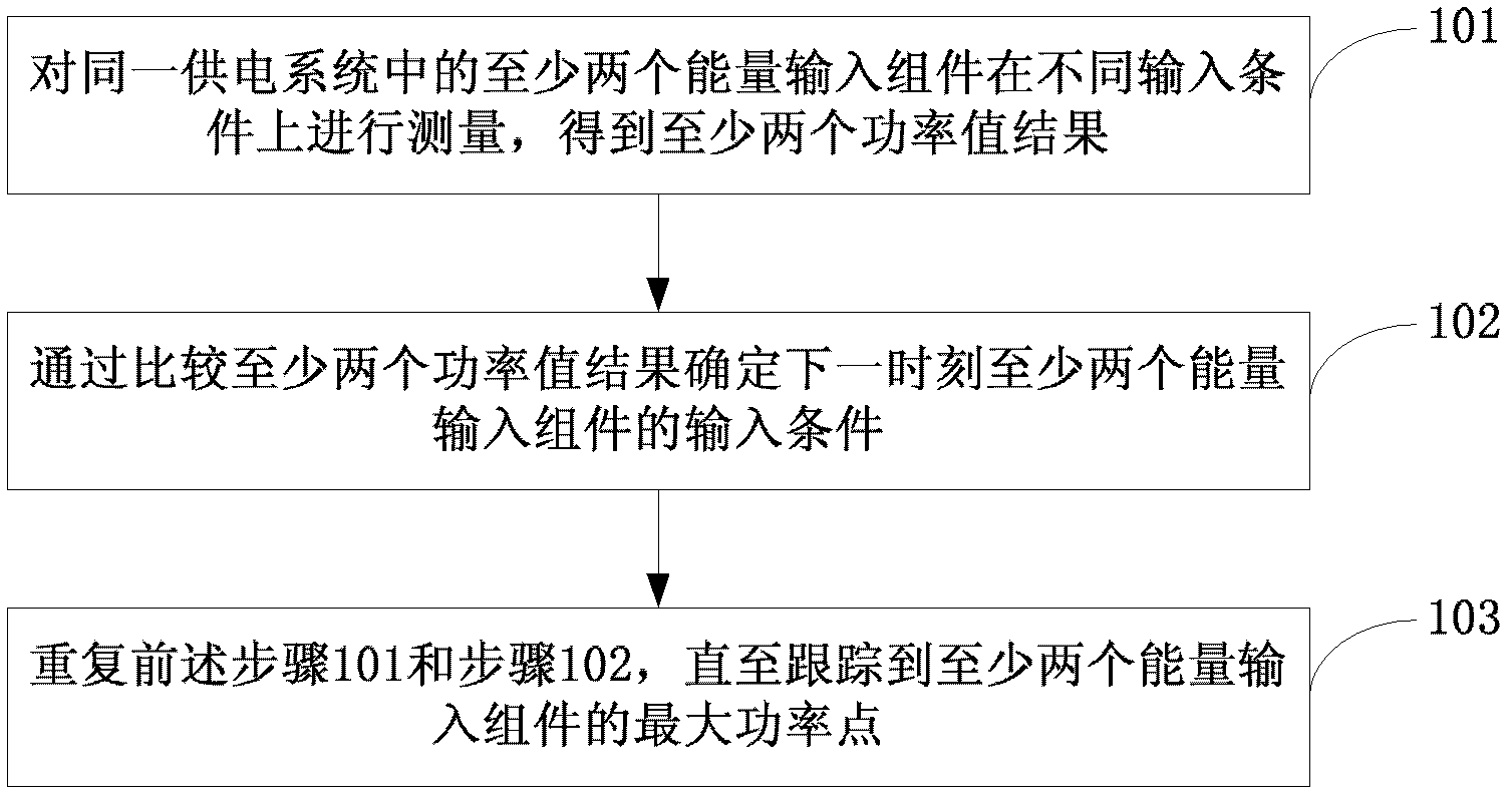
[0034] see figure 1 , is the flow chart of the first embodiment of the maximum power point tracking method of the present invention:
[0035] Step 101: Measure at least two energy input components in the same power supply system under different input conditions, and obtain at least two power value results.
[0036] In the embodiment of the present invention, the power supply system may be a solar photovoltaic power generation system, using solar photovoltaic panels as energy input components, or a wind power generation system, using wind turbine blades as energy input components. Different from power point scanning in serial mode in the prior art, the embodiment of the present invention measures at least two energy input components under different input conditions at the same time, so that by comparing each measurement result, the next step can be determined by parallel scanning. Input conditions of at least two energy input components at a time.
[0037] In this embodiment,...
no. 1 example
[0061] see image 3 , is a block diagram of the first embodiment of the maximum power point tracking device of the present invention:
[0062] The device includes: a measuring unit 310 , a determining unit 320 and a tracking unit 330 .
[0063] Wherein, the measurement unit 310 is used to measure at least two energy input components in the same power supply system under different input conditions, and obtain at least two power value results;
[0064] A determining unit 320, configured to determine the input conditions of the at least two energy input components at the next moment by comparing the at least two power value results;
[0065] The tracking unit 330 is configured to repeatedly execute the functions of the measurement unit 310 and the determination unit 320 until the maximum power points of the at least two energy input components are tracked.
no. 2 example
[0066] see Figure 4A , is a block diagram of the second embodiment of the maximum power point tracking device of the present invention:
[0067] The device includes: a measurement unit 410 , a determination unit 420 , a tracking unit 430 and an adjustment unit 440 .
[0068] Wherein, the scanning unit 410 is used to measure at least two energy input components in the same power supply system under different input conditions, and obtain at least two power value results;
[0069] A determining unit 420, configured to determine the input conditions of the at least two energy input components at the next moment by comparing the at least two power value results;
[0070] A tracking unit 430, configured to repeatedly execute the functions of the measurement unit 410 and the determination unit 420 until the maximum power point of the at least two energy input components is tracked;
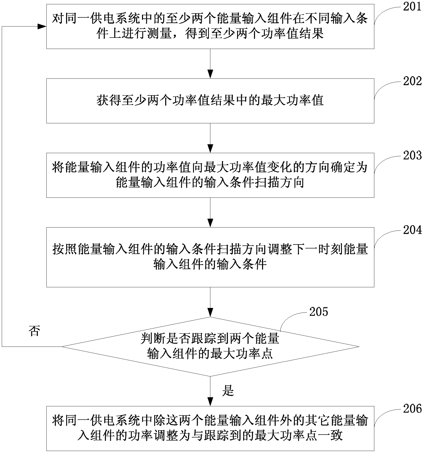
[0071] The adjustment unit 440 is configured to adjust the power of other energy input components ...
PUM
 Abstract
Description
Claims
Application Information
 - R&D
- Intellectual Property
- Life Sciences
- Materials
- Tech Scout
- Unparalleled Data Quality
- Higher Quality Content
- 60% Fewer Hallucinations
Browse by: Latest US Patents, China's latest patents, Technical Efficacy Thesaurus, Application Domain, Technology Topic, Popular Technical Reports.
© 2025 PatSnap. All rights reserved.Legal|Privacy policy|Modern Slavery Act Transparency Statement|Sitemap|About US| Contact US: help@patsnap.com


