
Recording device and control method of the recording device

A technology of a recording device and a control method, which is applied to power transmission devices, printing, transfer materials, etc., can solve the problems of difficulty in using the height or position of the light sensor, and the reduction of throughput, so as to prevent failures and prevent the reduction of throughput Effect

Active Publication Date: 2012-08-08
SEIKO EPSON CORP
View PDF6 Cites 1 Cited by
  • Summary
  • Abstract
  • Description
  • Claims
  • Application Information

AI Technical Summary

Problems solved by technology

[0004] In addition, the phenomenon that the recording head is separated from the recording medium occurs not only when the recording head runs aground at the level difference that the recording medium has, but also when the recording head runs aground at the edge of the recording medium, and in this case, there is a difficulty Problems detecting the height or position of steps using optical sensors, etc.
Therefore, the conventional countermeasure to prevent the degradation of recording quality when the recording head is stranded is to drive the recording head at a low speed, but there is a problem of causing a decrease in throughput.

Method used


Image

  • Recording device and control method of the recording device
  • Recording device and control method of the recording device
  • Recording device and control method of the recording device

Examples


no. 1 approach

[0033] Hereinafter, embodiments of the present invention will be described with reference to the drawings.

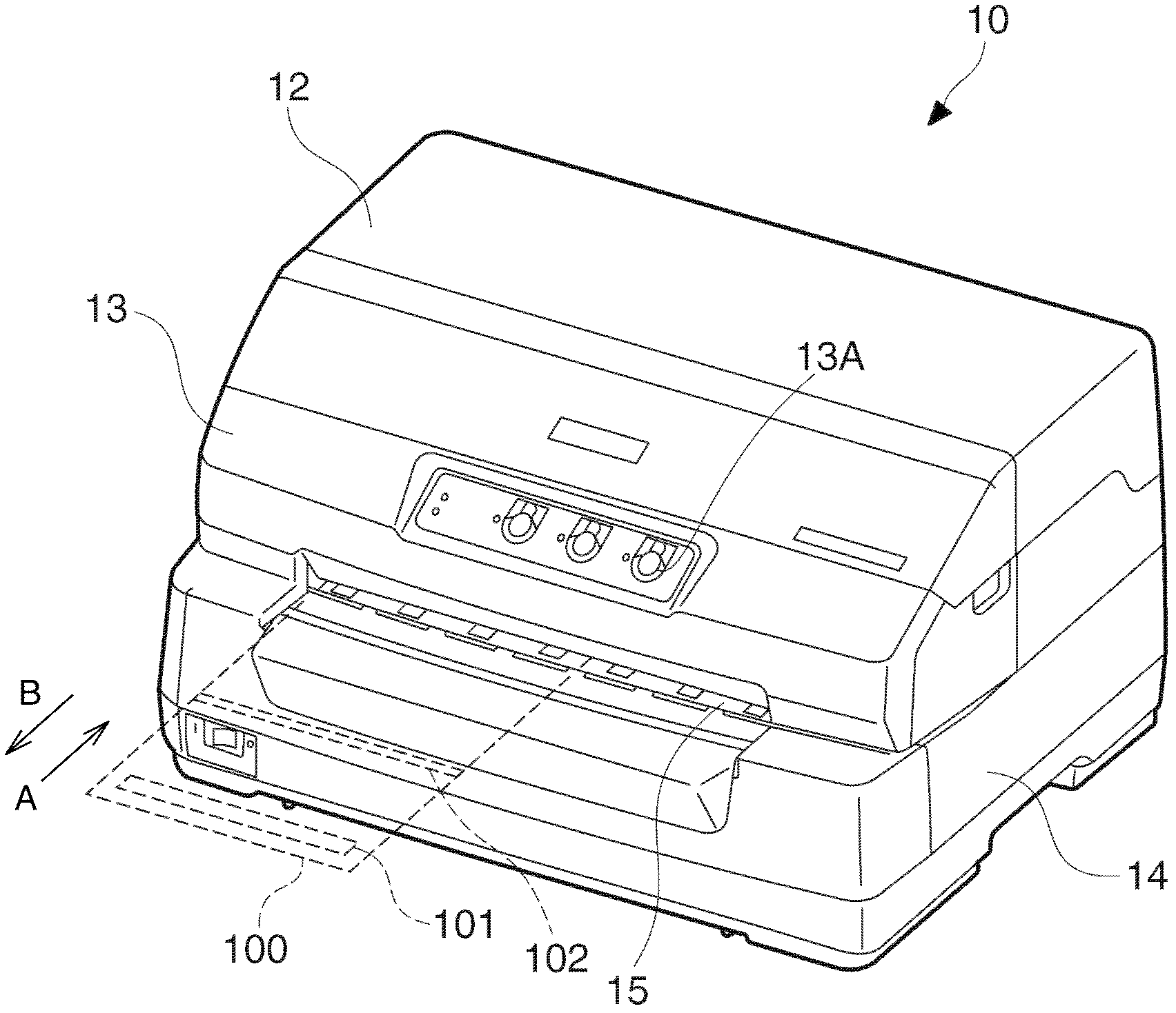
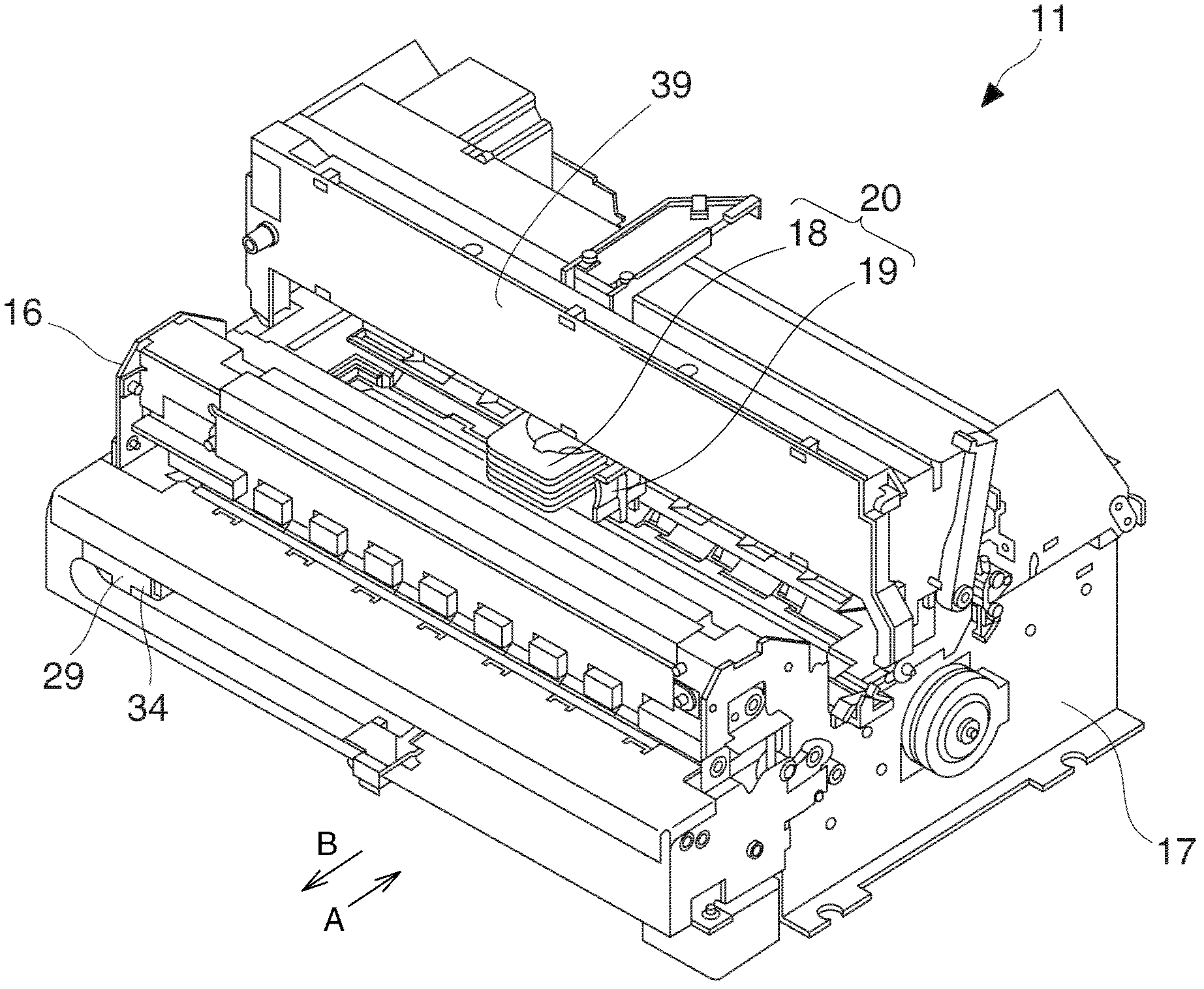
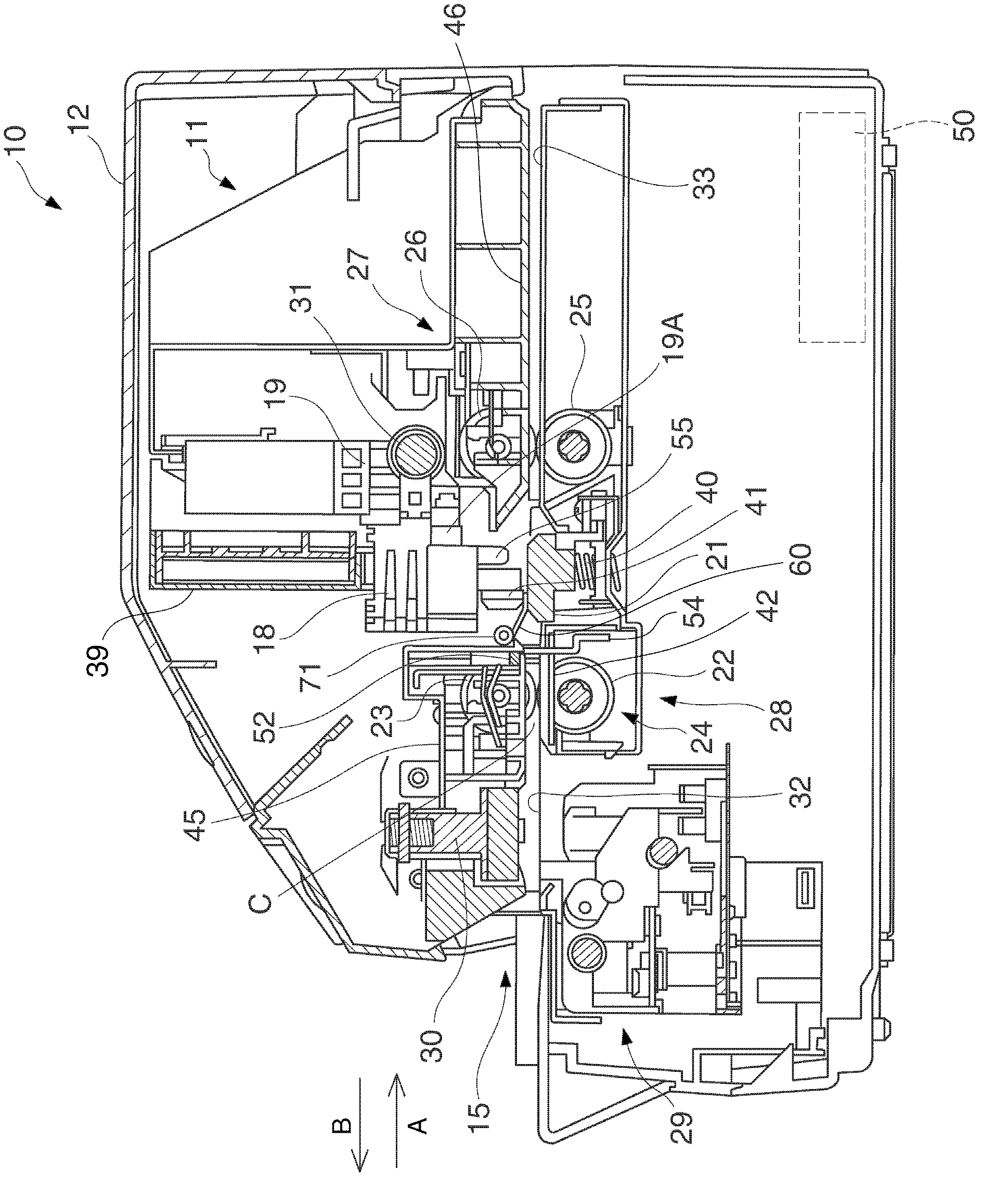
[0034] figure 1 It is a perspective view showing the appearance of a printer (recording device) 10 (hereinafter referred to as printer 10) as a recording device to which the first embodiment of the present invention is applied. The printer 10 of this embodiment includes a recording head 18 having a plurality of recording needles (refer to figure 2 as well as image 3 ) Of the click-and-print printer, from the recording head 18 through the ink ribbon to eject the recording needle to the recording medium, thereby forming dots on the recording surface of the recording medium to record characters, images, marks, etc. The image or the like recorded by the printer 10 includes one or more lines and is recorded line by line.

[0035] The printer 10 is connected to the host computer 68 as an external device ( Figure 7 ), the printer 10 executes recording (printing) in units of line...


PUM


Abstract

The invention provides a recording device and a control method of the recording device. The recording device comprises a recording head (18) and a recording head moving part of a bracket driving motor (35) for reciprocating motion of the recording head (18). A CPU (61) is used for control to record media in a moving scope of the recording head (18) and to move the recording head (18) to perform recording at the same time. The CPU (61) makes the recording head (18) cross the edge of the recording media to move to a recoding starting position of a recording medium (100) when at the beginning of recording, the recording head (18) is deviating from the position of the recording medium. Based on a moving starting position, an upper limit of a moving speed of the recording head (18) is changed into a speed lower than a set upper limit speed. Accordingly, faults caused by the stranding of the recording head on the recording media can be avoided and higher recording quality can be kept.

Description

Technical field [0001] The present invention relates to a recording device that records images on a recording medium, and a control method of the recording device. Background technique [0002] Conventionally, in a recording device that scans a recording head on a recording medium to perform recording, when the recording head lands on a recording medium with a change in the thickness of the recording medium, or a recording medium with a thickness, the recording head is removed from the recording medium. If you leave, there will be some problems such as not getting records. In order to solve this problem, for example, there is a technology that detects a change in the thickness of the recording medium using an optical sensor, and when the thickness changes, the driving speed of the recording head is reduced (for example, refer to Patent Document 1). [0003] Patent Document 1: JP No. 7-117277 [0004] In addition, the phenomenon that the recording head is separated from the recordin...

Claims


Application Information

Patent Timeline
Patent Type & Authority Applications(China)
IPC IPC(8): B41J2/225B41J25/24
Inventor 有贺勇一
Owner SEIKO EPSON CORP
Learn More