
Image forming apparatus

An image and reading part technology, which is applied in the fields of electric recording process using charge pattern, equipment for electric recording process using charge pattern, and electric recording technology, which can solve image quality degradation, poor image quality, and optical components. Deformation and other problems, to achieve the effect of inhibiting image quality degradation and inhibiting adhesion

Inactive Publication Date: 2012-08-01
KONICA MINOLTA BUSINESS TECH INC
View PDF4 Cites 2 Cited by
  • Summary
  • Abstract
  • Description
  • Claims
  • Application Information

AI Technical Summary

Problems solved by technology

[0004] However, the image forming apparatus described in Patent Document 1 has a problem that the image quality of an image read by a reader tends to deteriorate due to long-term use.
As a result, the optics inside the reader may be deformed by heat
As a result, in the image forming apparatus described in Patent Document 1, the image quality of the image read by the reader may deteriorate.
In addition, in the image forming apparatus described in Patent Document 1, the image quality of the image read by the reader may be degraded due to heat generated in the image forming unit being transferred to the reader.

Method used


Image

  • Image forming apparatus
  • Image forming apparatus
  • Image forming apparatus

Examples


other Embodiment approach

[0046] The image forming apparatus according to the invention of the present application is not limited to the image forming apparatus 1 described in the above-mentioned embodiment, and changes can be made within the scope of the gist thereof.

[0047] In addition, the rotation speed of the fan 50 does not have to be constant. For example, when the temperature around the image forming apparatus 1 is relatively high, or when the number of sheets of paper P printed by the image forming apparatus 1 is relatively large, the control unit (not shown) of the image forming apparatus 1 turns the fan The rotation speed of 50 is controlled to be relatively large. Furthermore, in this case, the control unit can operate the fan 50 for a constant time even after the printing is completed. On the other hand, when the temperature around the image forming apparatus 1 is relatively low, or when the number of sheets of paper P printed by the image forming apparatus 1 is relatively small, as lon...


PUM


Abstract

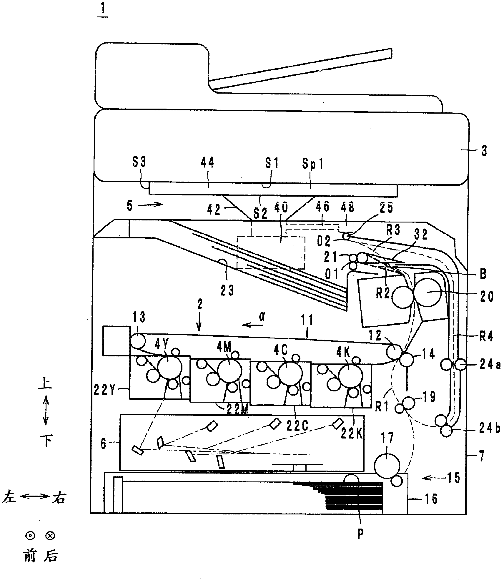
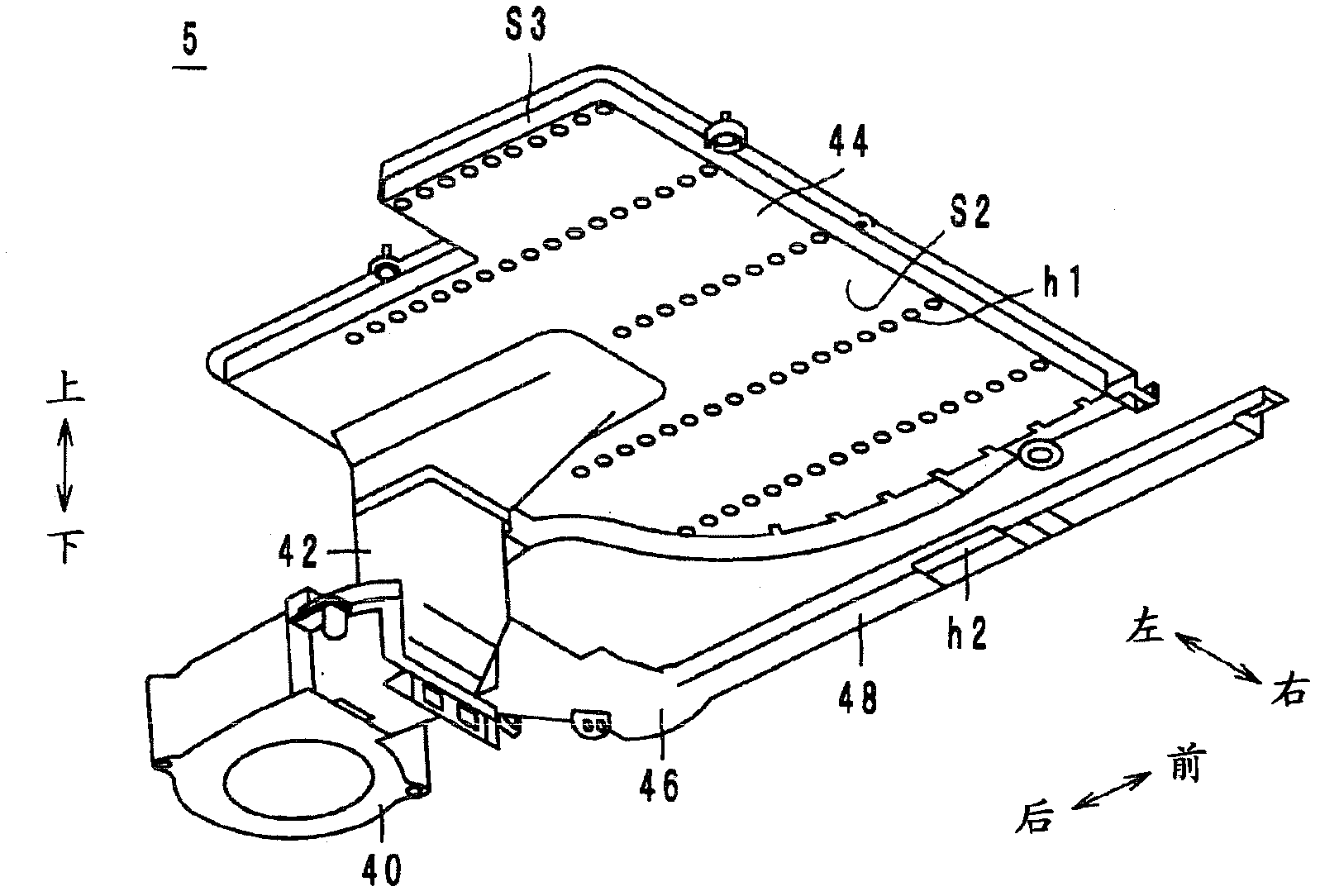
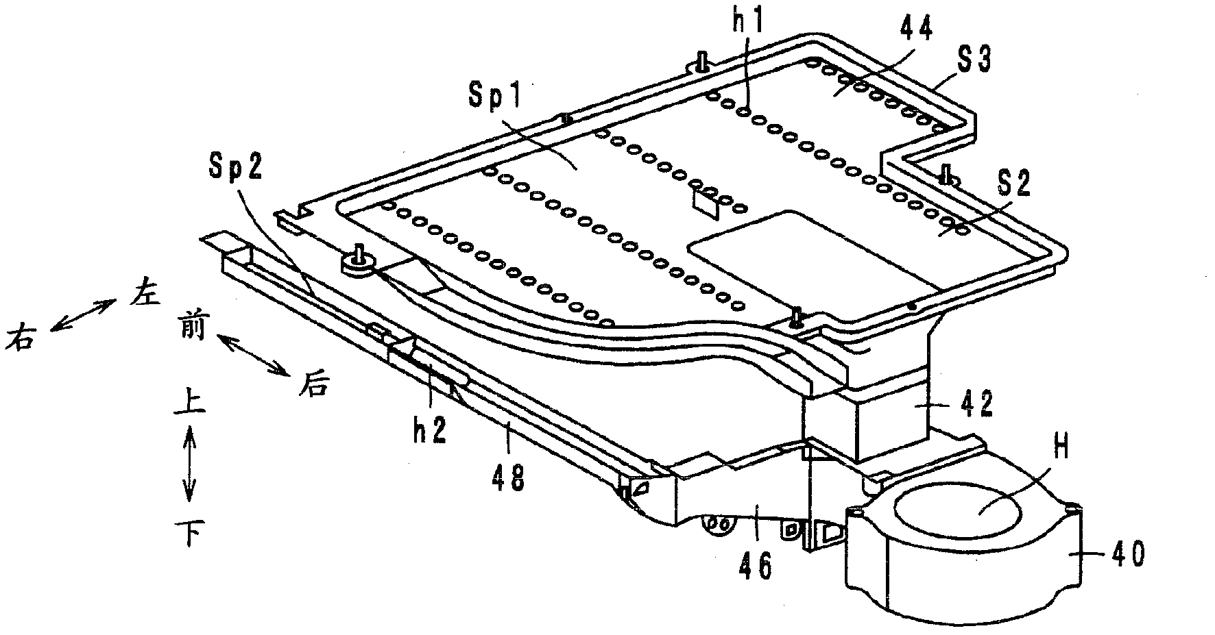
The invention provides an image forming apparatus, paper bonding can be inhibited, worsening of quality of an image read by a reading part can be inhibited. The image forming apparatus comprises a scanner (3) reading image data of a document; a printer section (7) for printing the image data read by the scanner as a toner with paper (P) and provided with a sheet tray (23) for output of paper (P) printed with the toner image. The scanner (3) is provided with a lower surface (S1) disposed opposite to the sheet tray (23); the cooler section (5) sucking air outside the printer section (7) and the scanner (3), and sends the air along the lower surface (S1) and blows the air to the sheet being fed to the tray.

Description

technical field [0001] The present invention relates to an image forming apparatus, and more particularly, to an image forming apparatus including a reading unit and a printing unit. Background technique [0002] As a conventional image forming apparatus, for example, the image forming apparatus described in Patent Document 1 is known. This image forming apparatus includes a reader and an image forming unit. The reader is a scanner that reads an image of a document. The image forming unit is provided below the reader, and prints a toner image on recording paper. In addition, a stacking portion for stacking printed recording paper is provided on the upper surface of the image forming portion. [0003] In the image forming apparatus described in Patent Document 1 configured as described above, a cooling fan is provided near the discharge port of the image forming section in order to prevent the recording sheets discharged to the stacking section from sticking to each other....

Claims


Application Information

Patent Timeline
Patent Type & Authority Applications(China)
IPC IPC(8): G03G21/20G03G15/00
CPCG03G21/206G03G21/203G03G15/6573
Inventor 峰村太辅浅仓直一
Owner KONICA MINOLTA BUSINESS TECH INC
Learn More