Nailing cap

A technology for shooting nails and nail caps, which is applied in the direction of nails, U-shaped nails, connecting components, etc., which can solve problems such as laborious and time-consuming installation, and achieve the effect of saving production and installation costs

Inactive Publication Date: 2012-08-01
胡长存
View PDF3 Cites 2 Cited by
  • Summary
  • Abstract
  • Description
  • Claims
  • Application Information

AI Technical Summary

Problems solved by technology

[0003] In order to overcome the time-consuming and labor-intensive shortcomings of the existing fixing components, the invention provides a "nail shooting cap". The nail shooting cap can not only fix the lamp panel, but also integrate the original fixing components. It will feel extra light and simple to use

Method used


Image

  • Nailing cap
  • Nailing cap
  • Nailing cap

Examples


Embodiment Construction

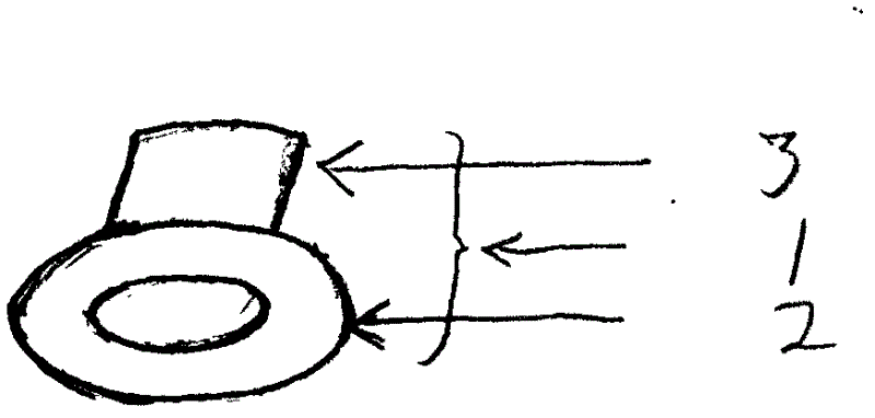
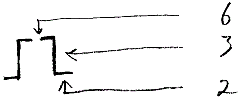
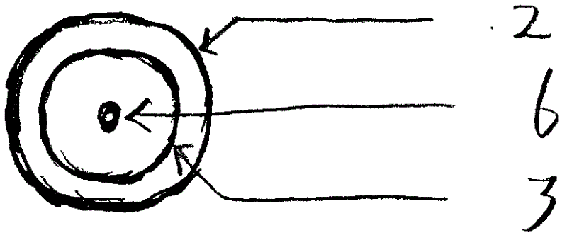
[0011] exist Figure 4 In the process, first stick the central round hole 4 (C) of the lamp panel 5 on the center position of the roof, then fasten the cap top 3 of the nail cap 1 on the central round hole 4 (C) of the lamp panel 5, and then use Nail the nail cap 1 on the roof with the nail gun, then straighten the lamp panel 5, and finally fix the remaining round holes 4 (A, B, D, E) in the same way.

[0012] Note: When we shoot nails, we should buckle the "discarded shells" upside down on the tip of the steel nail and nail the nail cap to the roof together. In this way, the gun jumping can be prevented to a certain extent. If you still use the original fixing parts for fixing, you can first drill a hole in the center of the roof with an electric hammer, then insert the expansion plug into the hole, and then stick the central round hole 4 (C) of the lamp panel 5 on the hole, Fasten the nail cap 1, use a self-tapping screw to pass through the nail hole 6 of the nail cap 1, a...


PUM


Abstract

The invention discloses a nailing cap 1. A base plate 5 of a flat lamp or a ceiling lamp is mounted quickly and conveniently; and the nailing cap 1 is formed by integrating the conventional fixing components. When being used, the nailing cap 1 is only required to be buckled on circular holes 4 (A, B, C, D and E) at the bottom of the base plate 5 and nailed on the roof by a nailing gun. According to the method, the production and mounting costs are reduced to a certain extent.

Description

technical field [0001] The invention relates to a fixing piece for the chassis of a "flat lamp or ceiling lamp", especially the fixing piece has a shape similar to a "top hat". Background technique [0002] At present, the chassis of the known public panel lamp or ceiling lamp is composed of lamp panel, foot, lamp panel screw hole and expansion plug and self-tapping screw required for fixing the lamp panel. Here, the foot, screw hole, expansion plug, self-tapping screw Although tapping screws can play the role of fixing the lamp panel, it is time-consuming, laborious and not safe to install. Specifically, first use an electric hammer to drill holes in the roof - a lot of dust will be generated at this time, and it will happen to be stamped Wires or break the floor heating pipe - then use a small hammer to insert the expansion plug into the drilled hole, then pass the self-tapping screw through the screw hole of the lamp panel, and tighten it on the expansion plug with a scre...

Claims


Application Information

Patent Timeline
Patent Type & Authority Applications(China)
IPC IPC(8): F16B15/00
Inventor 胡长存
Owner 胡长存
Why Eureka
Try Eureka