Multi-stage piston compressor

一种压缩机、活塞式的技术,应用在多级活塞式压缩机领域,能够解决输入压力范围和压缩比窄等问题

Active Publication Date: 2012-08-01
LINDE AG
View PDF7 Cites 14 Cited by
  • Summary
  • Abstract
  • Description
  • Claims
  • Application Information

AI Technical Summary

Problems solved by technology

[0005] If the compression stages in a general-purpose multi-stage compressor are connected in series as a stepped compressor, and the output side of one compression stage is connected to the input side of the next compression stage, then in a general-purpose compressor, the pistons of the compression stages are connected to the common The drive train is connected and driven simultaneously, resulting in a fixed and constant piston stroke through the piston of the corresponding compression stage that limits the input pressure range and compression ratio of each compression stage to a narrow range

Method used


Image

  • Multi-stage piston compressor
  • Multi-stage piston compressor
  • Multi-stage piston compressor

Examples


Embodiment Construction

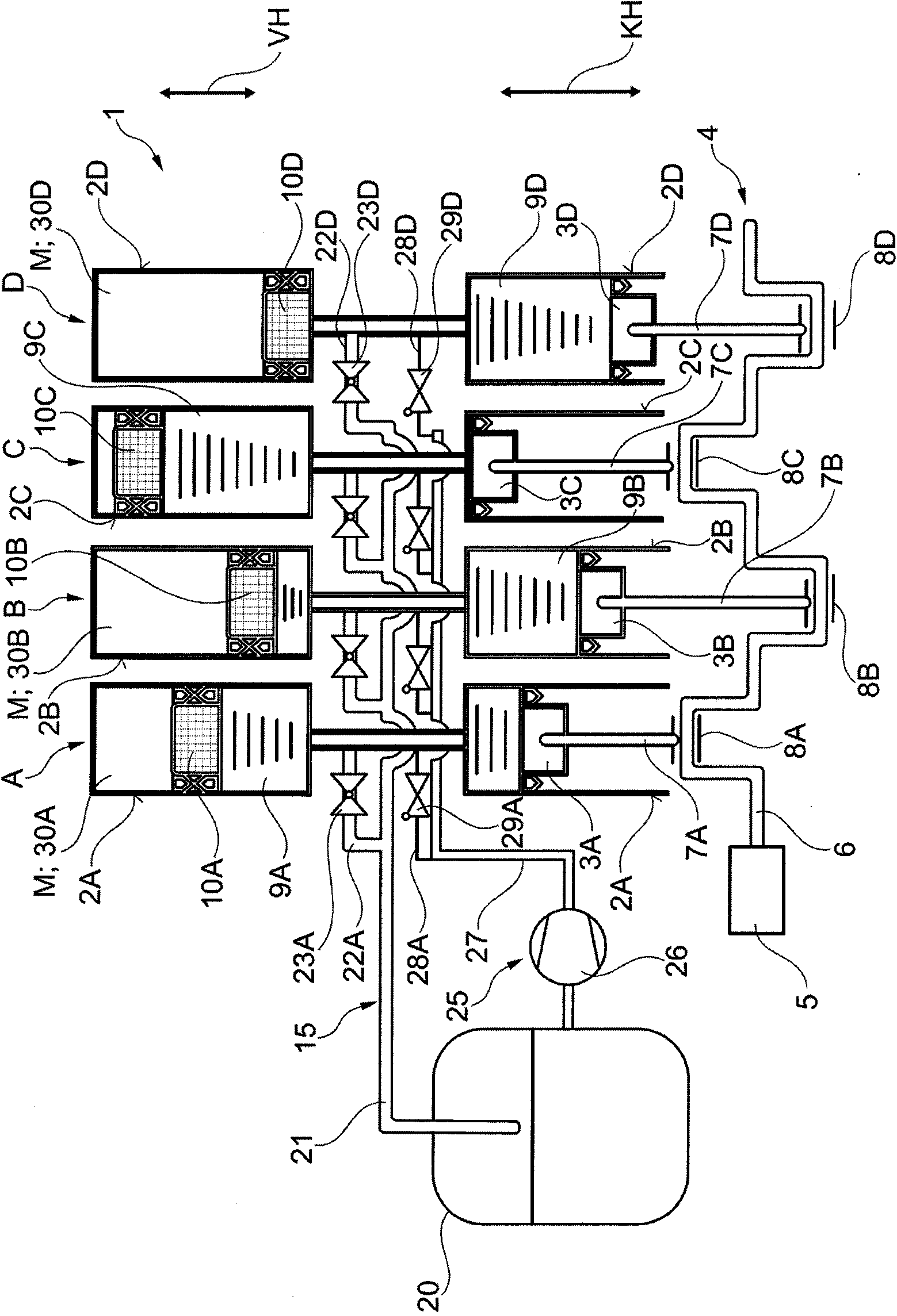
[0028] figure 1 A multi-stage piston compressor 1 according to the invention is shown, which in this embodiment comprises four compression stages A, B, C, D.

[0029] Each compression stage A, B, C, D comprises a piston 3A, 3B, 3C, 3D located in a compressor cylinder 2A, 2B, 2C, 2D so that it can move longitudinally. The pistons 3A-3D are drivingly connected with the common drive train 4 to jointly drive the pistons 3A-3D.

[0030] In the embodiment shown, the drive train 4 consists of a crank or eccentric shaft 6 driven by a drive motor 5, such as an electric motor or an internal combustion engine, wherein the pistons 3A-3D are each mechanically connected to the crankshaft 6 by connecting rods 7A-7D. Fittings 8A-8D can be introduced, wherein the connecting rods 7A-7D are hingedly connected to the crank or eccentric shaft 6 .

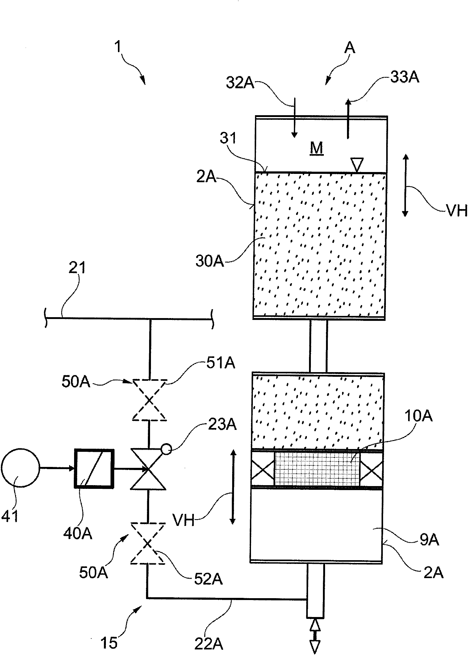
[0031] According to the invention, each piston 3A-3D is connected in the compressor cylinder 2A-2D by a liquid column 9A-9D consisting of an incompre...


PUM


Abstract

The compressor has a drivetrain mechanically connected to pistons provided in the compressor stages and longitudinally displaceable in compressor cylinders. The liquid columns accommodating the incompressible fluid are in communication with the pistons moved in the compressor cylinder. The compressor pistons are arranged in the compressor cylinders, for changing the liquid column for change of the compressor stroke (VH) of the compressor pistons. The liquid columns are made to communicate with an outlet.

Description

technical field [0001] The present invention relates to a multi-stage piston compressor for gaseous or cryogenically liquefied media having at least two compression stages operating in interaction with a common drive train for combined drives, each of which Each of the compression stages has pistons mechanically connected to the drive train that are positioned in the compressor cylinder so that they can move longitudinally. Background technique [0002] DE 10 2006 042 122 A1 discloses a general multistage piston compressor. [0003] The compressor is used to compress gaseous or liquid media such as gaseous or liquid hydrogen, nitrogen or natural gas. [0004] In a common multi-stage compressor, the pistons of a single compression stage are connected to a common driveline, and the pistons of a single compression stage are mechanically connected to the driveline, and the pistons of the compression stages are jointly driven by the driveline. The piston stroke performs the pis...

Claims


Application Information

Patent Timeline
Patent Type & Authority Applications(China)
IPC IPC(8): F04B25/00F04B53/10
CPCF04B41/06F04B15/08F04B3/00F04B39/0011F04B25/005F04B23/06F04B35/04F04B39/0022F04B39/0094F04B39/10F04B39/122F04B49/22F05B2210/12F05B2210/14Y10S417/00F04B9/1095F04B9/117F04B9/1176F04B53/141F04B53/142
Inventor R·阿德莱尔M·普凡德G·西贝特
Owner LINDE AG
Why Eureka
Try Eureka