Charge engine injected with low-entropy mixed-combustion liquefied gas
A gas liquefied source and engine technology, which is applied to combustion engines, internal combustion piston engines, engine components, etc., can solve the problems of low heat transfer coefficient of liquefied gas, lack of wide application of engines, complex systems, etc.
- Summary
- Abstract
- Description
- Claims
- Application Information
AI Technical Summary
Problems solved by technology
Method used
Image


Examples
Embodiment 1
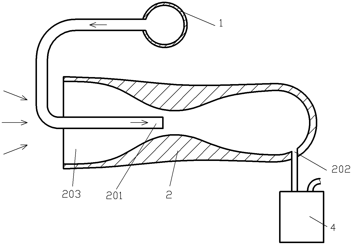
[0055] like figure 1 The shown low-entropy mixed gas liquefied injection engine includes a gas liquefied source 1, a jet pump 2 and a working mechanism 3, and the gas liquefied source 1 and the jet pump power fluid injection port of the jet pump 2 201 communicates, the jet pump gas outlet 202 of the jet pump 2 communicates with the working medium inlet of the working mechanism 3, and the jet pump low-pressure gas inlet 203 of the jet pump 2 communicates with the atmosphere; the gas liquefied source 1 The gas liquefied substance in is set as liquid oxygen, and the pressure bearing capacity of the communication channel between the gas liquefied substance source 1 and the jet pump power fluid injection port 201 is greater than 3MPa; by adjusting the jet pump power fluid jet port The flow rate of the gas liquefied substance in 201 and / or the pressure of the gas in the gas liquefied substance, and the type and size of the jet pump 2 are adjusted so that the gas pressure in the jet ...
Embodiment 2
[0059] like figure 2 The shown low-entropy mixed gas liquefied injection engine includes a gas liquefied source 1, a jet pump 2 and a suction engine 4, the gas liquefied source 1 and the jet pump power fluid injection port of the jet pump 2 201 communicates, the jet pump gas outlet 202 of the jet pump 2 communicates with the working medium inlet of the suction engine 4, the gas liquefied matter in the gas liquefied matter source 1 is set as liquid nitrogen, and the gas liquefied matter The pressure bearing capacity of the communication channel between the source 1 and the jet pump power fluid injection port 201 is greater than 5 MPa; pressure, and adjust the type and size of the jet pump 2, so that the gas pressure in the jet pump gas outlet 202 of the jet pump 2 is greater than 3MPa.
[0060] Optionally, the suction engine 4 can be replaced by an explosive exhaust engine or a short-pressure gas-charged engine.
Embodiment 3
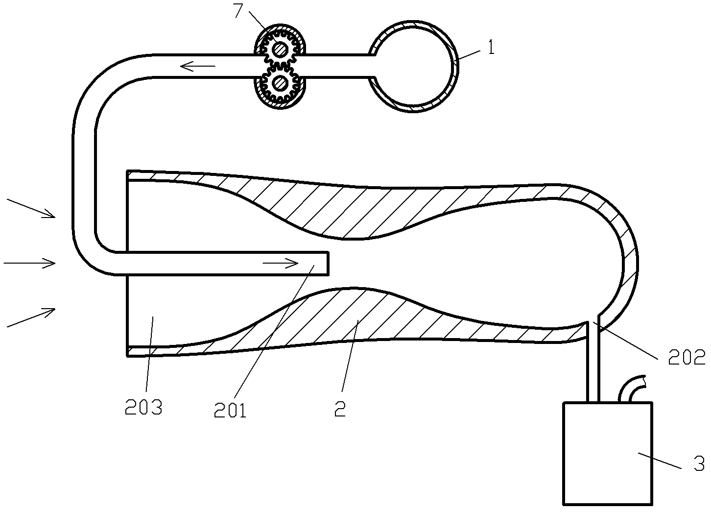
[0062] like image 3 The difference between the shown low-entropy mixed gas liquefied injection engine and that of Embodiment 1 is that a high-pressure fluid is provided on the communication channel between the gas liquefied source 1 and the jet pump power fluid injection port 201. Pump 7, the pressure bearing capacity of the communication channel between the gas liquefied source 1 and the jet pump power fluid injection port 201 is greater than 10MPa; And / or the pressure of the gas in the gas liquefied product, and adjust the type and size of the jet pump 2, so that the gas pressure in the jet pump gas outlet 202 of the jet pump 2 is greater than 8 MPa.
PUM
 Abstract
Description
Claims
Application Information
 - R&D Engineer
- R&D Manager
- IP Professional
- Industry Leading Data Capabilities
- Powerful AI technology
- Patent DNA Extraction
Browse by: Latest US Patents, China's latest patents, Technical Efficacy Thesaurus, Application Domain, Technology Topic.
© 2024 PatSnap. All rights reserved.Legal|Privacy policy|Modern Slavery Act Transparency Statement|Sitemap