
Method for assembling heavy core-pulling mechanism of large injection mould

A technology for injection molds and core-pulling mechanisms, applied in the field of assembly of heavy-duty core-pulling mechanisms, can solve the problems of difficult assembly, labor and time-consuming, easy to damage core-pulling sliders, etc., and achieve the effect of solving difficult assembly and avoiding damage

Inactive Publication Date: 2012-08-01
宁海胜利模具有限公司
View PDF3 Cites 2 Cited by
  • Summary
  • Abstract
  • Description
  • Claims
  • Application Information

AI Technical Summary

Problems solved by technology

[0002] Large-scale injection molds refer to injection molds with a weight greater than 50 tons. The heavy-duty core-pulling mechanism in a large-scale injection mold often weighs nearly ten tons. The model core is loaded into the moving mold carrier plate, and then the core-pulling slider is inserted into the moving model core and the moving mold carrier plate along the slot hole in the core-pulling direction, and then the core-pulling seat is set on the core-pulling slider, and the cover Upper core-pulling seat cover and fixed; because the weight of the core-pulling slider and the core-pulling seat is too heavy, the above method is too difficult to assemble, time-consuming and labor-intensive, and it is easy to damage the profile of the core-pulling slider; therefore, now The existing technology has the problems and shortcomings of labor and time-consuming, easy to damage the surface of the core-pulling slider

Method used


Image

  • Method for assembling heavy core-pulling mechanism of large injection mould
  • Method for assembling heavy core-pulling mechanism of large injection mould
  • Method for assembling heavy core-pulling mechanism of large injection mould

Examples


Embodiment Construction

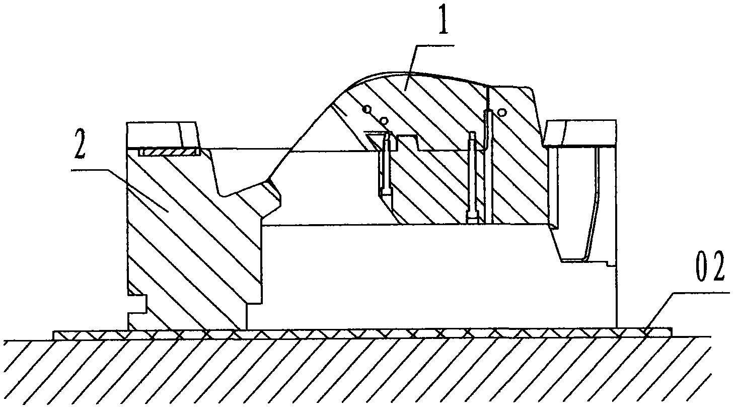
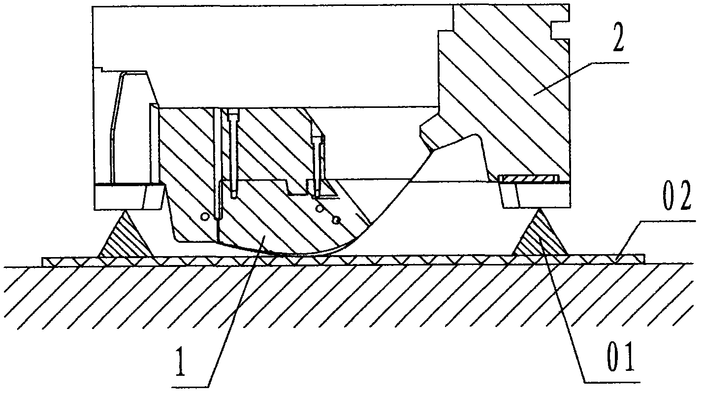
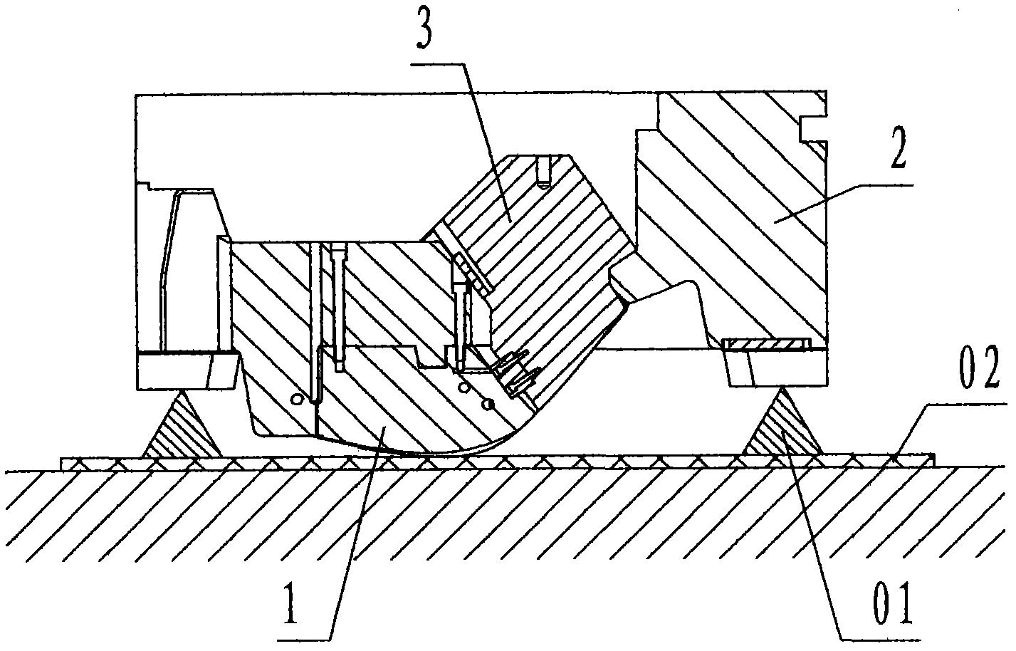
[0024] refer to Figure 1 to Figure 7 , the assembly method of the heavy-duty core-pulling mechanism of a large-scale injection mold of the present invention is an assembly process method, and the assembly process method is: using a crane,

[0025] Step 1, hoisting the moving model core 1 into the moving model carrier plate 2 in the forward direction;

[0026] Step 2, hoist the movable mold carrier plate 2 and the dynamic model core 1 and turn it to 180°, make the bottom surface of the movable mold carrier plate 2 face up and use the support 01 to level the bottom surface of the movable mold carrier plate 2; the support 01 is a jack;

[0027] Step 3: Use a crane to hang the bottom surface of the core-pulling slider 3 through the lifting ring, lift and slide the profile of the core-pulling slider 3 vertically along the corresponding profile of the movable model core 1, and insert it into the movable mold carrier plate 2 and the movable mold core 1 In the core pulling slot;

...


PUM


Abstract

The invention discloses a method for assembling a heavy core-pulling mechanism of a large injection mould. Firstly, a movable mould core is forwardly mounted in a movable mould carrier plate, and then the movable mould carrier plate is turned by 180 degrees, so that the bottom of the movable mould carrier plate faces up and the movable mould carrier plate is leveled. Secondly, the bottom of a core-pulling slider is lifted by a lifting ring, and the core-pulling slider is vertically lifted along a profile and inserted into core-pulling slots of the movable mould carrier plate and the movable mould core. Thirdly, a core-pulling sliding seat is guided into the movable mould carrier plate in a lifted manner along the direction of a T-shaped groove at the tail of the core-pulling slider. Fourthly, a core-pulling insert is inserted into the space between the movable mould carrier plate and the core-pulling slider in a lifted manner and is fixedly connected with the movable mould carrier plate through screws. Fifthly, a core-pulling cover plate covers the core-pulling sliding seat in a lifted manner and is fixedly connected with the movable mould carrier plate through screws. By the aid of the technical scheme, the method overcomes the shortcomings that the prior art is labor-consuming and time-consuming, and the profile of a core-pulling slider is easily damaged. By means of inverted assembly, assembly of the heavy core-pulling mechanism of the large injection mould is labor-saving and time-saving, and the profile of the core-pulling slider is not damaged.

Description

technical field [0001] The invention relates to an assembly method of an injection mold, in particular to an assembly method of a heavy-duty core-pulling mechanism of a large-scale injection mold for assembling a heavy-duty core-pulling mechanism into a large-scale injection mold. Background technique [0002] Large-scale injection molds refer to injection molds with a weight greater than 50 tons. The heavy-duty core-pulling mechanism in a large-scale injection mold often weighs nearly ten tons. The model core is loaded into the moving mold carrier plate, and then the core-pulling slider is inserted into the moving model core and the moving mold carrier plate along the slot hole in the core-pulling direction, and then the core-pulling seat is set on the core-pulling slider, and the cover Upper core-pulling seat cover and fixed; because the weight of the core-pulling slider and the core-pulling seat is too heavy, the above method is too difficult to assemble, time-consuming a...

Claims


Application Information

Patent Timeline
IPC IPC(8): B29C45/33
Inventor 汪进兵
Owner 宁海胜利模具有限公司
Learn More