
Power supply circuit for low voltage test system of locomotive

A technology for testing systems and power circuits, applied in electrical components, output power conversion devices, etc., can solve problems such as malfunction, abnormal power outage of AC load, failure to work, etc., to solve malfunction, ensure normal work, structure simple effect

Inactive Publication Date: 2012-07-25
ZHUZHOU CSR TIMES ELECTRIC CO LTD
View PDF7 Cites 2 Cited by
  • Summary
  • Abstract
  • Description
  • Claims
  • Application Information

AI Technical Summary

Problems solved by technology

When the switch KK2 is closed, due to the capacitive characteristics of the DC110V power module, an instantaneous surge current will be generated. After the surge current exceeds the withstand value of the leakage protection circuit breaker, the leakage protection circuit breaker will act and cut off the external AC220V and the test circuit. connection, but this kind of action of the leakage protection circuit breaker is a malfunction, which will cause abnormal power failure of the AC load (such as shutdown due to abnormal power failure of the industrial computer, etc.)
[0004] In theory, closing the switch KK2 once will increase the capacitance of the DC110V power module, although in theory the capacitance of the DC110V power module can be gradually increased by closing the switch KK2 several times in a row to reduce the impact at the moment of power-on current to avoid the misoperation of the leakage protection circuit breaker, but this method does not work in actual operation

Method used


Image

  • Power supply circuit for low voltage test system of locomotive
  • Power supply circuit for low voltage test system of locomotive
  • Power supply circuit for low voltage test system of locomotive

Examples


Embodiment Construction

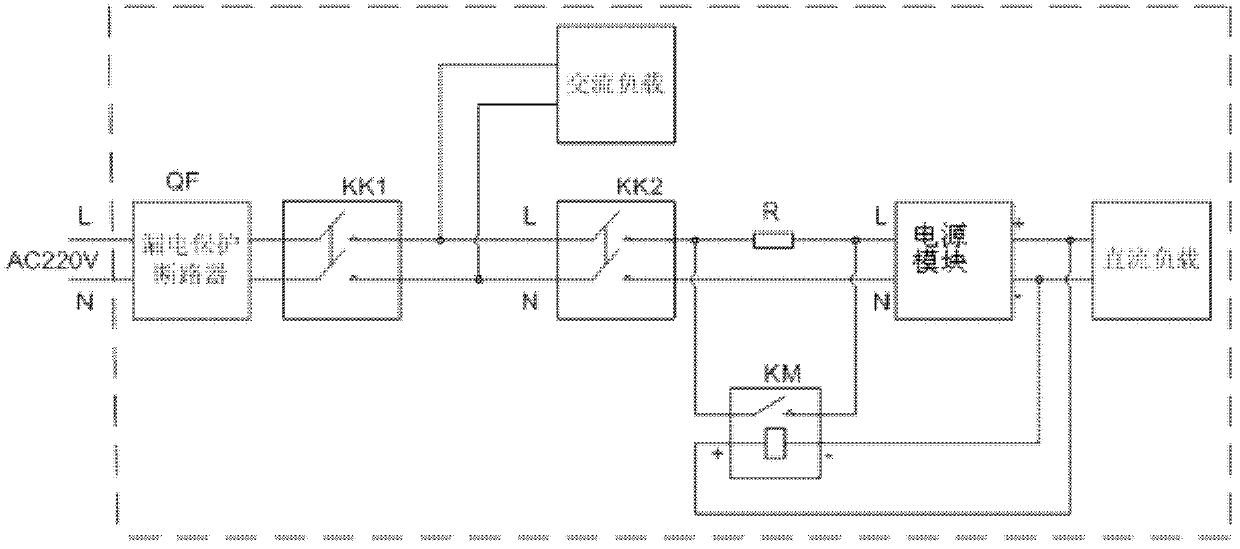
[0013] like figure 2 As shown, an embodiment of the present invention includes a leakage protection circuit breaker QF, two switches KK1 and KK2, an AC load, a power module, a DC load, a leakage protection circuit breaker QF, a first switch KK1, a second switch KK2, a power supply The module and the DC load are connected in sequence, and the AC load is connected in parallel between the first switch KK1 and the second switch KK2, and also includes a current limiting resistor R and a contactor KM, and the current limiting resistor R is connected to the second switch KK2 and the power supply Between the modules, the contactor KM is connected in parallel between the power module and the DC load, and the normally open contact switch of the contactor KM is connected in parallel with the current limiting resistor R; the power module includes a transformer T, a rectifier bridge, and a capacitor branch circuit. More than two capacitors are connected in parallel, the transformer T is c...


PUM


Abstract

The invention discloses a power supply circuit for a low voltage test system of a locomotive. The power supply circuit comprises an electric leakage protection circuit breaker, a switch, an alternating current load, a power supply module and a direct current load, wherein the electric leakage protection circuit breaker, the switch, the power supply module and the direct current load are sequentially connected, the alternating current load is connected in parallel between the switch and the power supply module, the power supply circuit also comprises a current limiting resistor and a contactor, the current limiting resistor is connected between the switch and the power supply module, the contactor is connected in parallel between the power supply module and the direct current load, and a normally-open contact switch of the contactor is connected in parallel with the current limiting resistor. The power supply circuit has the advantages that the structure is simple, the current limiting resistor and the contactor are added on the basis of not changing the original circuit system structure, the problem of malfunction of the electric leakage protection circuit breaker caused by excessive impact current at the electrification moment is solved, and the normal work of the circuit is ensured.

Description

technical field [0001] The invention relates to a circuit breaker, in particular to a power supply circuit of a locomotive low-voltage test system. Background technique [0002] like figure 1 As shown, the virtual frame is the power supply circuit of the low-voltage test system installed with the leakage protection circuit breaker, mainly including the leakage protection circuit breaker QF, switch KK1, switch KK2, DC110V power supply, DC load, and AC load. The AC220V power supply is obtained from the outside. First, the current passes through the leakage protection circuit breaker QF, and then the AC load is operated by closing the switch KK1, and then the DC110V power supply is operated by closing the switch KK2. The DC110V power supply converts the AC220V power into DC110V DC power for subsequent DC loads circuit use. [0003] According to the general use sequence, the switch KK1 is closed first, and the switch KK2 is in the disconnected state. At this time, the AC load ...

Claims


Application Information

Patent Timeline
IPC IPC(8): H02M1/32
Inventor 谭利红陈明奎李小文苏理李进进刘伟良余长超万加林刘丽君
Owner ZHUZHOU CSR TIMES ELECTRIC CO LTD
Learn More