


Quick Research
Generate reliable direction feasibility study reports for your R&D in just a few steps.

Technical Q&A
Discover and master advanced knowledge NOW. Basics, ideas, possibilities, all at once.

Find Solutions
As an expert in R&D theories, this can generate solutions to your technical problems instantly.

Evaluate Feasibility
Analyze your overall solution with one click, know your potential R&D risks in advance.

Monitor Landscape
Get weekly tech updates, stay abreast of the latest tech innovations and key insights.
Radiation field uniformity calibration positioner
A positioning device and uniformity technology, applied in the field of radiation field uniformity calibration positioning device, can solve the problems of increased measurement uncertainty, uneven local field strength, thick vertical connecting rod, etc., to reduce the impact and simplify the calibration The effect of testing the operation process and improving efficiency
- Summary
- Abstract
- Description
- Claims
- Application Information
AI Technical Summary
Problems solved by technology
Method used
Image


Examples
Embodiment 1
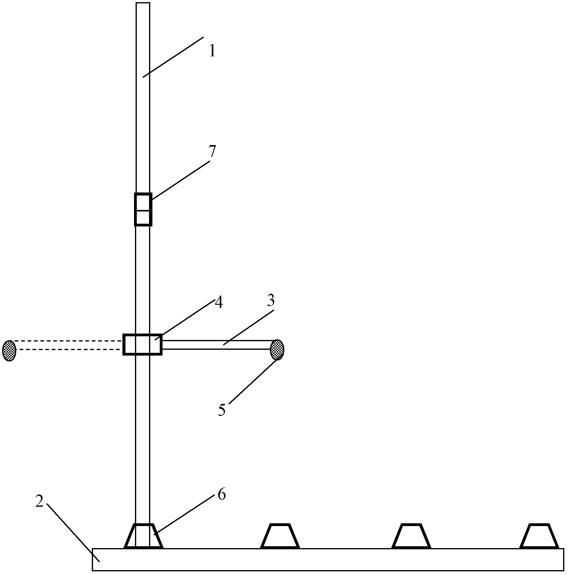
[0041] Radiation field uniformity verification positioning device, such as figure 2 As shown, it includes a vertical connecting rod 1, a bottom plate 2, a horizontal connecting rod 3, and a horizontal sleeve 4;
[0042] The bottom end of the vertical connecting rod 1 is fixed on the bottom plate 2;
[0043] The horizontal sleeve 4 is sleeved on the outside of the vertical connecting rod 1 and can slide axially along the vertical connecting rod 1;
[0044] The horizontal sleeve 4 and / or the vertical connecting rod 1 are provided with an axial positioning mechanism (such as a positioning hole, a positioning pin, etc.), for the horizontal sleeve 4 to be positioned in the axial direction of the vertical connecting rod 1 fixed;
[0045] The horizontal connecting rod 3 has one end fixed on the horizontal sleeve 4 and perpendicular to the vertical connecting rod 1, and the other end is used to fix the electric field probe 5;
[0046] The cross-sectional area of the horizontal c...
Embodiment 2
[0049] Radiation field uniformity calibration positioning device such as image 3 As shown, it includes a vertical connecting rod 1, a horizontal connecting rod 3, a horizontal sleeve 4, a vertical sleeve 7, a base sleeve 6, and a bottom plate 2;
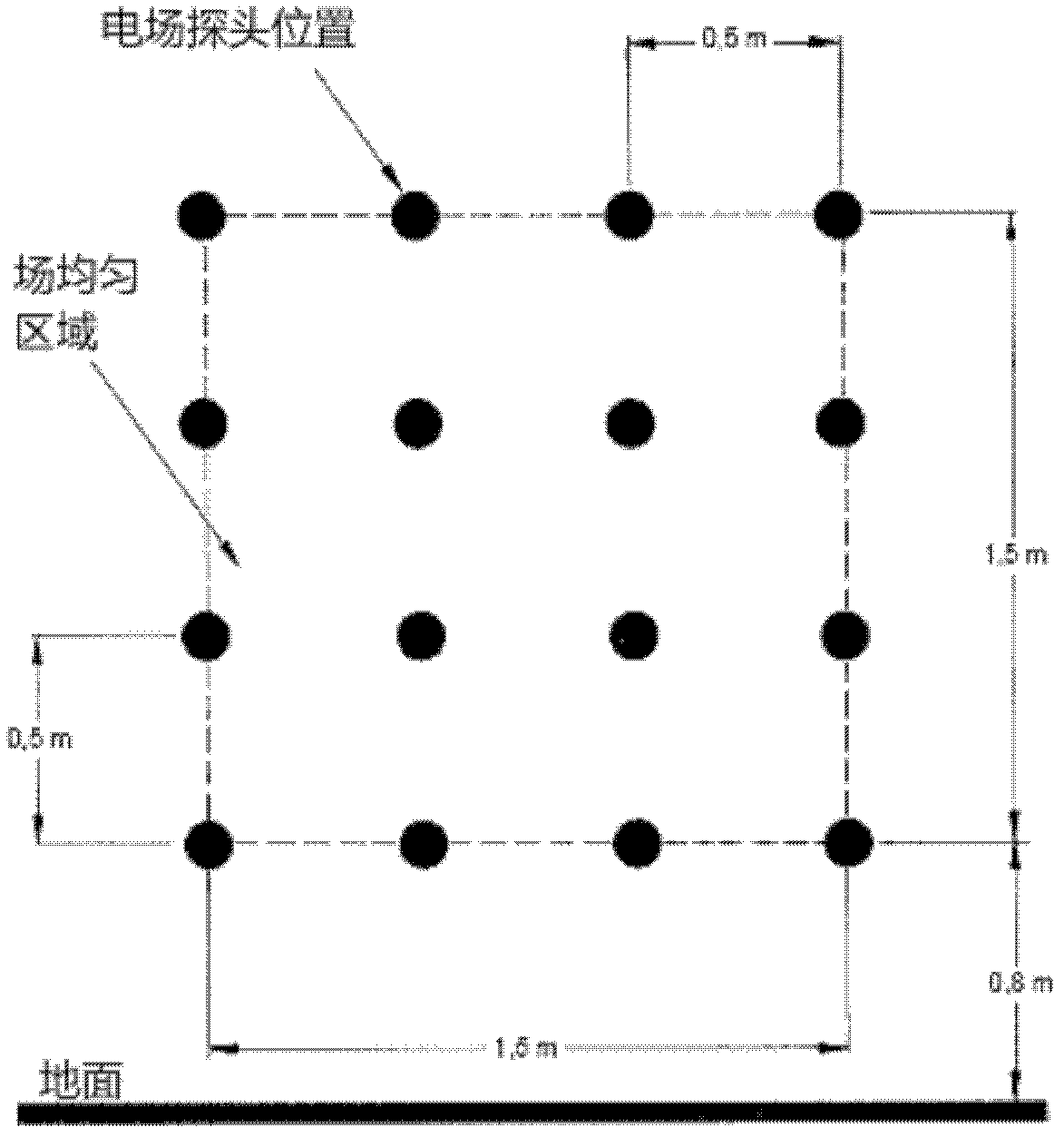
[0050] Described base sleeve 6 has multiple ( figure 2 4 in the center), a plurality of base sleeves 6 are fixed on the base plate 2 in a straight line, the axis of each base sleeve 6 is perpendicular to the base plate 2, and the distance between the axes of two adjacent base sleeves 6 is equal;
[0051] The bottom end of the vertical connecting rod 1 is detachably accommodated and fixed in one of the base sleeves 6;
[0052] Described vertical connecting rod 1 can be multi-section ( image 3 There are two sections in the middle), and the multi-section vertical connecting rod 1 is connected and fixed through the vertical sleeve 7 to form the entire vertical connecting rod 1;
[0053]The distance from the electric field probe to ...
Embodiment 3
[0060] Radiation field uniformity calibration positioning device such as Figure 5 As shown, it includes two vertical connecting rods 1, two base sleeves 6, two horizontal sleeves 4, a bottom plate 2, a horizontal connecting rod 3, and an electric field probe 5;
[0061] The two base sleeves 4 are respectively fixed on the base plate 2, and the axis of the base sleeve 2 is perpendicular to the base plate 2;
[0062] The bottom ends of the two vertical connecting rods 1 are accommodated and fixed in the two base sleeves 4 respectively;
[0063] Described vertical connecting rod 1 can be multi-section ( Figure 5 The middle is two sections), and the multi-section vertical connecting rod is connected and fixed through the vertical sleeve 6 to form the entire vertical connecting rod 1;
[0064] The two horizontal sleeves 4 are respectively sleeved on the outside of the two vertical connecting rods 1, and can slide axially along the set of vertical connecting rods 1 respectively;...
PUM
 Abstract
Description
Claims
Application Information
 - R&D Engineer
- R&D Manager
- IP Professional
- Industry Leading Data Capabilities
- Powerful AI technology
- Patent DNA Extraction
Browse by: Latest US Patents, China's latest patents, Technical Efficacy Thesaurus, Application Domain, Technology Topic, Popular Technical Reports.
© 2024 PatSnap. All rights reserved.Legal|Privacy policy|Modern Slavery Act Transparency Statement|Sitemap|About US| Contact US: help@patsnap.com