
Rock mass anisotropy osmotic coefficient in-situ test method and device thereof

A technology of anisotropy and permeability coefficient, applied in the field of in-situ testing of anisotropic permeability coefficient of rock mass, can solve the problems of high cost, large limitations, complex test methods, etc., and achieve simple structure, reasonable design and convenient operation. Effect

Inactive Publication Date: 2012-07-25
CHANGSHA UNIVERSITY OF SCIENCE AND TECHNOLOGY
View PDF5 Cites 17 Cited by
  • Summary
  • Abstract
  • Description
  • Claims
  • Application Information

AI Technical Summary

Problems solved by technology

The single-hole single-stage water pressure test uses parameters such as the flow rate in the hole, the pressure in the hole, the radius of the water hole, and the length of the water section to calculate the permeability coefficient of the rock mass, but the anisotropic permeability characteristics of the rock mass cannot be considered. The permeability coefficient of the rock mass is equivalent to the isotropic permeability coefficient of the rock mass, and its test results have relatively large limitations.
The single-hole three-stage water pressure method needs to arrange the direction of the water pressure hole perpendicular to the direction of the crack, which is not applicable to the situation where the water pressure hole can only pass through a group of crack surfaces, and its limitations are also relatively large
However, the cross-hole pressure water test process and test method are complicated, expensive, and the test is not easy to succeed, so it is rarely used in engineering.

Method used


Image

  • Rock mass anisotropy osmotic coefficient in-situ test method and device thereof
  • Rock mass anisotropy osmotic coefficient in-situ test method and device thereof
  • Rock mass anisotropy osmotic coefficient in-situ test method and device thereof

Examples


Embodiment Construction

[0013] The present invention will be further described below with reference to the drawings and specific embodiments.

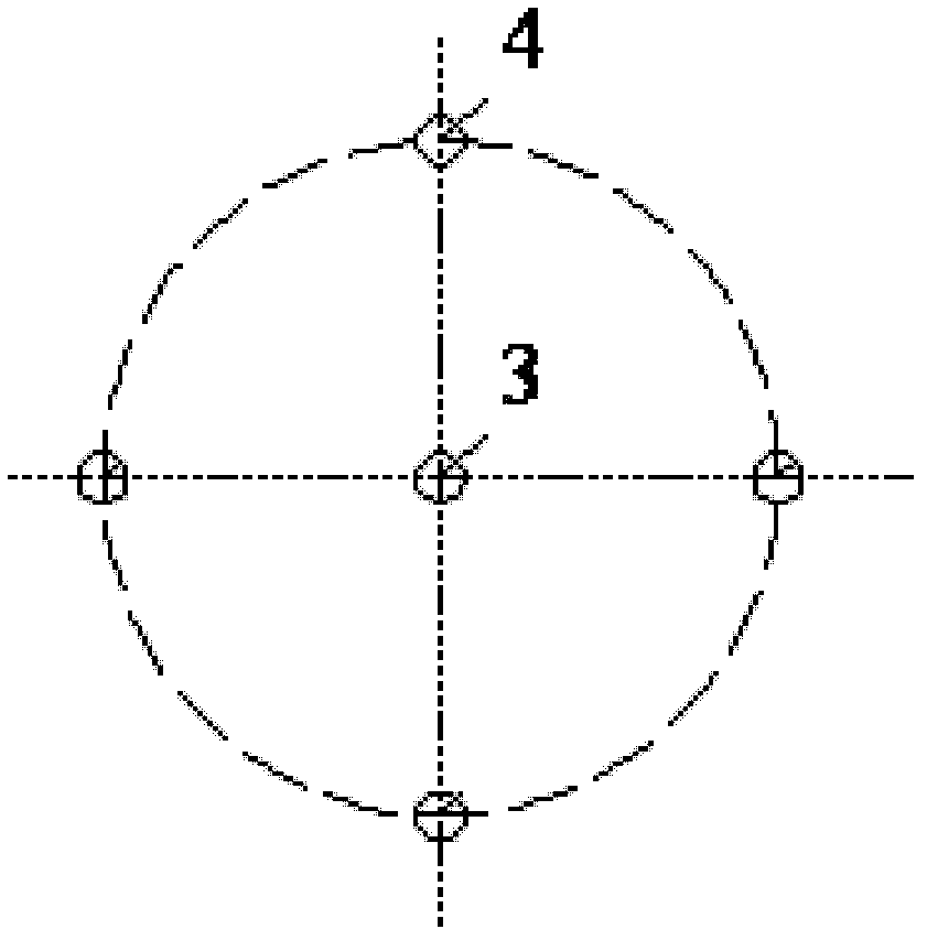
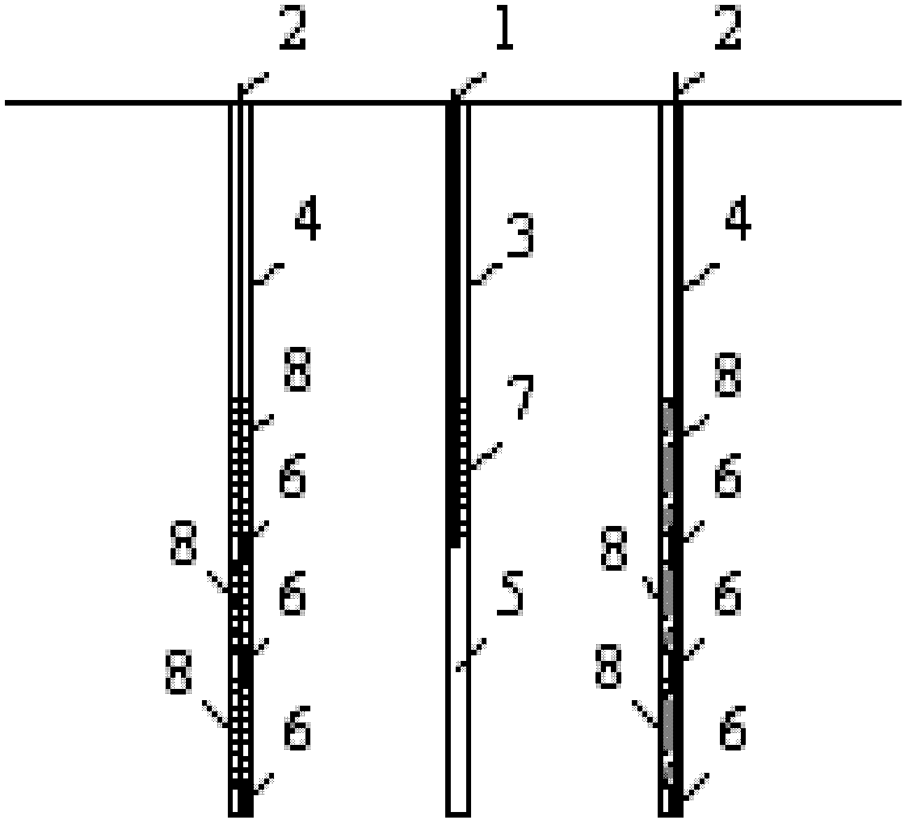
[0014] See figure 1 with figure 2 , With the pressurized water hole 3 as the center, 4 pressurized holes 4 are evenly arranged in the circumferential direction on a circle with a radius of 3 to 5 meters. The length of the pressurized water hole 3 is equal to the length of each pressurized hole 4, 3 is provided with a high pressure water stop plug 7 to form a water pressure section 5, the water inlet pipe 1 passes through the high pressure water stop plug 7 and communicates with the water pressure section 5, the length of the water pressure section 5 of the water pressure hole 3 is 5-10 meters, The bottom elevation of each seepage hole 4 is the same as the bottom height of the pressurized water hole 3. Each pressurized hole 4 is parallel to the pressurized water hole 3, and each pressurized hole 4 is equipped with three osmometers 6 The positions of the 3 piezo...


PUM

PropertyMeasurementUnit
lengthaaaaaaaaaa

Abstract

The invention discloses a rock mass anisotropy osmotic coefficient in-situ test method and a device thereof. At least four osmotic pressure holes (4) are uniformly and circumferentially distributed in a circumference with the radius being 3-5meters by adopting a water pressure hole (3) as a center; the length of a water pressure section (5) of the water pressure hole (3) is 5-10meters; three osmometers (6) are arranged in each osmotic pressure hole and are respectively corresponding to an upper end part, a lower end part and a midpoint of the water pressure section (5) of the water pressure hole (3); a water pressure test is required to reach a steady flow state, i.e. the pressure and the flow of the water pressure hole (3) as well as the pressure of each osmometer (6) are required to reach and keep in a continuous steady state; in a test process, the pressure and the flow of the water pressure hole (3) as well as the pressure of each osmometer (6) are kept to be recorded automatically and simultaneously; and a data recording time interval is not larger than 5 minutes. The invention provides the rock mass anisotropy osmotic coefficient in-situ test method and the device thereof which can take osmotic performance of rock mass anisotropy into consideration, and have a wide application range.

Description

Technical field [0001] The invention relates to an in-situ testing method for anisotropic permeability coefficient of rock mass, in particular to a testing method for the permeability tensor of rock mass used in the fields of water conservancy and hydropower engineering, traffic engineering, petroleum engineering and the like, especially for orthogonal anisotropy Measurement of permeability coefficient of heterogeneous rock mass. Background technique [0002] Under the existing technical conditions, the permeability coefficient of rock mass can be tested by the single-hole single-stage water pressure test method, the single-hole three-stage water pressure test method and the cross-hole water pressure test method. The single-hole single-stage water pressure test uses parameters such as the flow rate in the hole, the pressure in the hole, the radius of the water pressure hole and the length of the water pressure section to calculate the permeability coefficient of the rock mass, bu...

Claims


Application Information

Patent Timeline
Patent Type & Authority Applications(China)
IPC IPC(8): G01N15/08
Inventor 蒋中明付宏渊秦卫星伍东卫
Owner CHANGSHA UNIVERSITY OF SCIENCE AND TECHNOLOGY
Learn More