
Underground cavity volume detection method and underground cavity volume detection device

A cavity and volume technology, applied in the field of geology and detection, can solve problems such as increased detection difficulty, decreased detection accuracy, and roof damage in the burn-out area

Active Publication Date: 2012-07-25
ENN SCI & TECH DEV
View PDF4 Cites 18 Cited by
  • Summary
  • Abstract
  • Description
  • Claims
  • Application Information

AI Technical Summary

Problems solved by technology

[0007] However, the current 3D seismic technology has the following shortcomings: 1. The implementation cost is high and the process is complicated: the implementation of the detection requires a large number of facilities and equipment, software and hardware support; the implementation process involves the use of explosives, the construction of shot point drilling, etc., which is relatively complicated
2. Higher risk: due to the application of the earthquake principle, it is necessary to bury explosives to detonate as shock waves, and the shock waves may cause damage to the roof of the burn-out area
3. There are certain limitations. As the depth of the burn-up area increases, its detection accuracy decreases and the detection difficulty increases (the method of predicting the thickness of coal seams and paleo-river scour zones by using seismic attributes, the Institute of Geophysical Exploration, China Coal Geology Administration , China Coal Geology, No. 10, 2010; Analysis of the effect of seismic data source selection on the effective identification of karst caves, College of Geological Science and Engineering, Shandong University of Science and Technology; Journal of Shandong University of Science and Technology (Natural Science Edition), No. 05, 2010)

Method used


Image

  • Underground cavity volume detection method and underground cavity volume detection device
  • Underground cavity volume detection method and underground cavity volume detection device
  • Underground cavity volume detection method and underground cavity volume detection device

Examples


Embodiment 1

[0069] Embodiment 1: distribution coefficient K d Determination of

[0070] By simulating the formation of underground cavities in the laboratory, the combustion, heating or gasification residues were taken to measure the adsorption characteristics. The specific operation is as follows: put the lignite gasification residues of Dayan Coalfield with a mass of M mg into the container, and prepare the concentration for a 1 mg / L, a 2 mg / L, a 3 mg / L, a 4 mg / L, a 5 mg / L tracer (fluorescein sodium) solution, the gasification residue is mixed with 1000ml of the solution, where M and a n The relationship satisfies: 0.0032≤a 5 / M4 / M3 / M2 / M1 / M≤0.0047, shake on the shaker for 48 hours, then filter the sample, and test the concentration of tracer (fluorescein sodium) in the filtrate to be b 1 mg / L,b 2 mg / L,b 3 mg / L,b 4 mg / L,b 5 mg / L.

[0071] by different a 1 mg / L, a 2 mg / L, a 3 mg / L, a 4 mg / L, a 5 mg / L different concentration test, according to K d =(a-b) / a Calcu...

Embodiment 2

[0075] Example 2: Application of Volume Detection in Underground Coal Gasification Burn-out Area

[0076] 1. Obtain the adsorption characteristics of the gasification residue on the tracer (sodium fluorescein):

[0077] Before gasification in the underground coal gasification furnace, the lignite in the area to be gasified was used for a simulated underground gasification combustion test, and the burned coal ash was tested with reference to Example 1 to obtain the adsorption characteristics of a specific tracer (sodium fluorescein) in it. (partition coefficient K d = 0.624).

[0078] 2. Strengthening measures for water disturbance in the burn-out area:

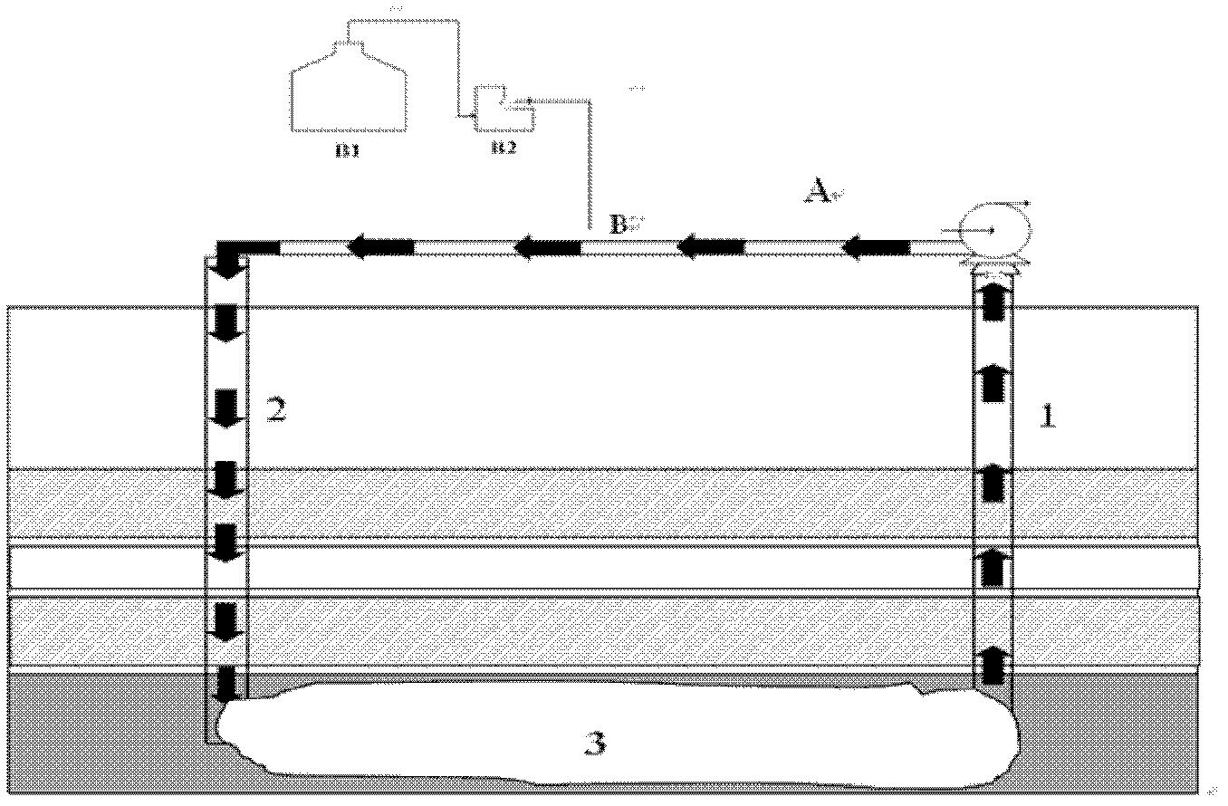
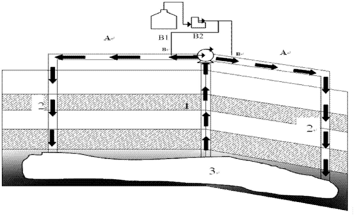
[0079] a. If figure 1 , after the gasified burn-out zone is filled with water, it needs to be disturbed by the ground water pump system, mainly using two connected boreholes 1 and 2 (with a diameter range of 150-400mm) to strengthen the circulation in the burn-out zone The water body is disturbed, and the water flow dire...

Embodiment 3

[0094] Example 3: Application of volume detection of oil shale burn-off zone

[0095] 1. Obtain the adsorption characteristics of the oil shale gob residue on the tracer (fluorescein sodium):

[0096] Before the oil shale is exploited, the oil shale samples in the area to be mined are obtained for testing under the same process conditions, and the oil shale gasification residue after the experiment is obtained by laboratory testing with reference to Example 1. Specific tracer (fluorescein sodium) Among them, the adsorption characteristics (partition coefficient).

[0097] 2. Strengthening measures for water disturbance in the burn-out area:

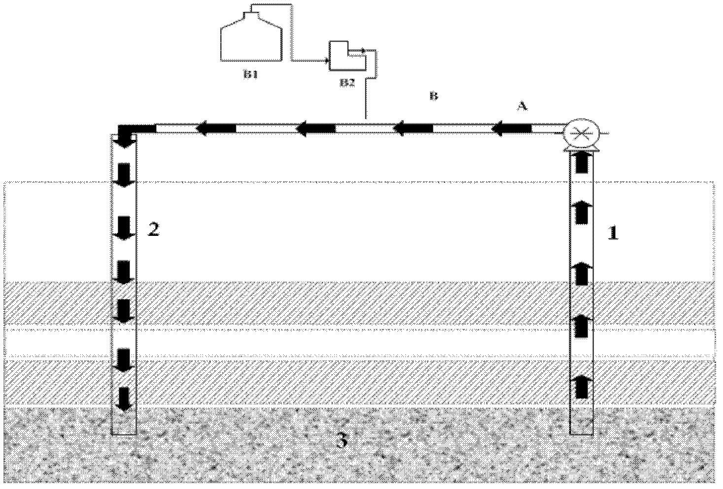
[0098] like image 3 After mining, the burn-out area is filled with water and needs to be disturbed by the surface water pump system. Two connected boreholes 1 and 2 (with a diameter range of 150-400mm) are used to circulate and strengthen the water disturbance in the burn-out area. , the water flow direction flows in the direction i...


PUM


Abstract

The invention belongs to the fields of geology and detection and relates to an underground cavity volume method and an underground cavity volume detection device. Particularly, the underground cavity volume detection method includes the following steps of 1) filling water into an underground cavity or keeping the underground cavity full of water; 2) adding detectable reagent of known quantity of A0mg into the underground cavity; 3) dispersing the detectable reagent in the step 2) in the water uniformly; 4) detecting concentration C' mg / L of the detectable reagent in the water; and 5) computing the volume V' of the water filled in the underground cavity according to the following formula, and obtaining the volume V of the underground: V=V'=A0 / C' / 1000m3. The invention further discloses the underground cavity volume detection device. The underground cavity volume method is capable of accurately measuring the volume of the underground cavity, particularly an empty combustion area and is short in cycle, free of risk, fine in repeatability and simple in process.

Description

technical field [0001] The invention belongs to the field of geology and detection, and relates to a method and a device for detecting the volume of an underground cavity. Background technique [0002] Underground coal gasification technology is a method of direct and controlled combustion of coal buried in the ground, and generates combustible gas through the thermal and chemical effects of coal. It has good safety, low investment, high efficiency, and less pollution. Etc. After the gasification is completed, the original coal seam is exploited by gasification to form a burn-out zone. [0003] Oil shale refers to a fine-grained sedimentary rock with high kerogen content and a considerable amount of oil that can be fractionated. The mass fraction of ash is greater than 40%, and the oil content is between 3.5% and 30%. The difference between oil shale and coal is that its ash mass fraction is greater than 40%. Oil shale must be heated to release hydrocarbon gases and liqui...

Claims


Application Information

Patent Timeline
IPC IPC(8): G01F17/00
Inventor 高宝平李金刚刘淑琴陈峰
Owner ENN SCI & TECH DEV
Learn More