
Fiber-optic loop structure wound in vertically symmetrical cross manner for fiber-optic gyroscope and winding method

A technology of fiber optic gyroscope and fiber optic ring, which is applied in the direction of Sagnac effect gyroscope, etc., which can solve the problems of stress, error and non-reciprocal error of optical path caused by fiber optic coil

Inactive Publication Date: 2014-12-31
BEIHANG UNIV
View PDF6 Cites 2 Cited by
  • Summary
  • Abstract
  • Description
  • Claims
  • Application Information

AI Technical Summary

Problems solved by technology

[0004] The current optical fiber coil winding mostly adopts the quadrupole symmetrical winding method. Although the optical path reciprocity is realized in the length of the optical fiber, the temperature-changing environment will generate a spatial temperature gradient, resulting in non-reciprocal errors in the optical path under temperature modulation.
In addition, the skeleton structure of the fiber ring that fixes the coil is mostly an "I"-shaped structure. The skeleton structure on the upper and lower sides and in the middle will constrain the fiber coil. When the vibration conditions and temperature change, the coil will be squeezed, resulting in the fiber coil. Stress is generated inside; some skeleton structures adopt the unilateral contact form with the upper edge removed. Although the thermal stress is reduced, there is a difference in heat flux between the contact side and the non-contact side, resulting in uneven distribution of the temperature field, resulting in errors

Method used


Image

  • Fiber-optic loop structure wound in vertically symmetrical cross manner for fiber-optic gyroscope and winding method
  • Fiber-optic loop structure wound in vertically symmetrical cross manner for fiber-optic gyroscope and winding method
  • Fiber-optic loop structure wound in vertically symmetrical cross manner for fiber-optic gyroscope and winding method

Examples


Embodiment Construction

[0034] The present invention will be further described in detail with reference to the accompanying drawings and embodiments.

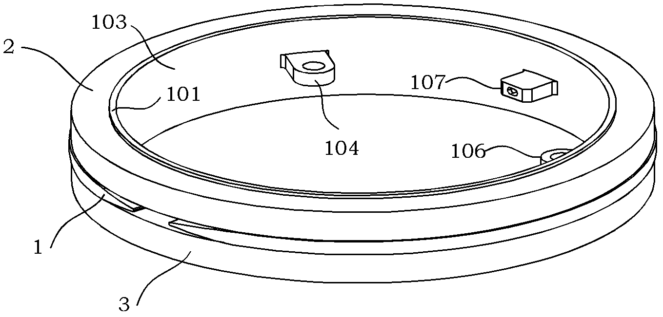
[0035] The present invention is an up-and-down symmetrical cross-winding optical fiber ring structure for the optical fiber gyroscope, such as figure 1 , figure 2 As shown, the optical fiber ring skeleton 1 is included.

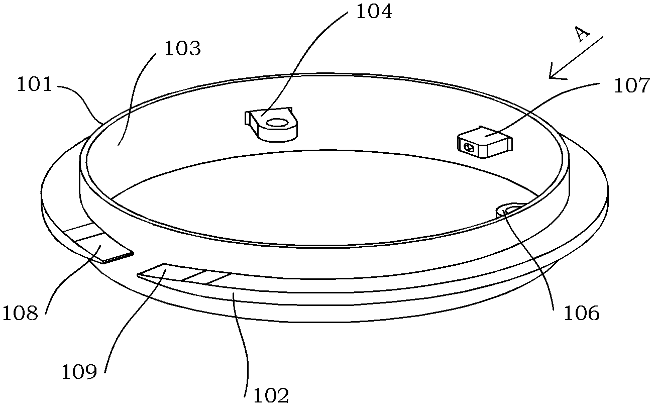
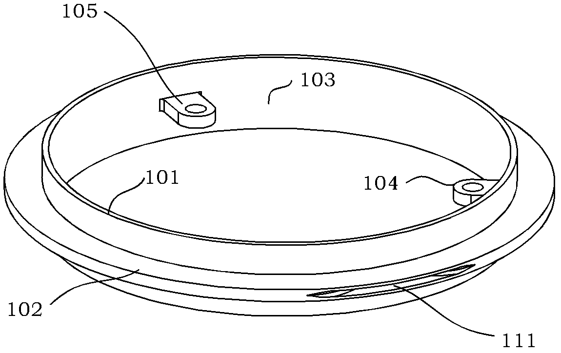
[0036] Optical fiber ring skeleton 1 such as figure 2 , Figure 2A , Figure 2B As shown, it includes a fiber post 101 , an intermediate flange 102 , an A lug 104 , a B lug 105 , a C lug 106 and a D lug 107 .

[0037] An intermediate flange 102 is provided around the periphery of the fiber column 101 , and the intermediate flange 102 is provided with an A fiber-passing slope 108 and a B fiber-passing slope 109 , and a fiber-passing gap 110 is formed between the A fiber-passing slope 108 and the B fiber-passing slope 109 .

[0038] Three lugs are evenly distributed on the inner wall 103 of the fiber column 101, namely A lug 104...


PUM


Abstract

The invention discloses a fiber-optic loop structure wound in a vertically symmetrical cross manner for a fiber-optic gyroscope. The fiber-optic loop structure comprises a fiber-optic loop skeleton which comprises a wrapping post and a middle flange, wherein the middle flange is arranged at the periphery of the wrapping post, the middle flange is provided with a fiber passing notch, horizontally run-though bellmouth orifices are arranged on the wrapping post and the middle flange and are located at the symmetrical positions of the fiber passing notch, and a fiber outlet is formed on the middle flange. A vertically symmetrical crosswise winding method for the fiber-optic gyroscope comprises the following steps: 1, setting the midpoint of an optical fiber at the position of the fiber passing notch of a fiber-optic loop; 2, winding the optical fiber; and 3, leading the optical fiber into the fiber outlet. According to the invention, a fiber-optic coil is divided into an upper part and a lower part, and each of the two parts has one side which is free of structural restriction and is not compressed in conditions of vibration and temperature variation; and through cross winding, the coils at two sides both have forward and reverse optical fibers which are the same in length, so that temperature gradients in axial and radial directions have the same temperature modulation effect on the optical fibers.

Description

technical field [0001] The invention relates to an up-and-down symmetrical cross-wound optical fiber ring structure and winding method for an optical fiber gyroscope, relates to the technical fields of optical fiber sensing, optical fiber gyroscope, and fiber winding, and is especially suitable for the application field of inertial navigation technology with harsh vibration and temperature conditions . Background technique [0002] Optical fiber gyroscope is a sensor used to detect the angular rate of carrier motion. It uses the optical Sagnac effect and optical fiber transmission principle to overcome a series of shortcomings of electromechanical gyroscope and laser gyroscope. It has all solid state, high reliability, dynamic With the advantages of large range, wide frequency band, small size and good vibration performance, it is widely used in aerospace, aviation, navigation, oil exploration and other fields. [0003] Optical fiber gyroscope is an opto-mechanical-electric...

Claims


Application Information

Patent Timeline
Patent Type & Authority Patents(China)
IPC IPC(8): G01C19/72
Inventor 贾明李彦宋凝芳
Owner BEIHANG UNIV
Learn More