Valve actuating mechanism for reciprocating motion body
A technology of reciprocating motion and gas distribution mechanism, which is applied in the direction of engine components, machines/engines, liquid variable displacement machinery, etc. It can solve the problems affecting the accuracy of gas distribution and the difficulty of valve control, so as to achieve the effect of precise gas distribution
- Summary
- Abstract
- Description
- Claims
- Application Information
AI Technical Summary
Problems solved by technology
Method used
Image
Examples
Embodiment 1
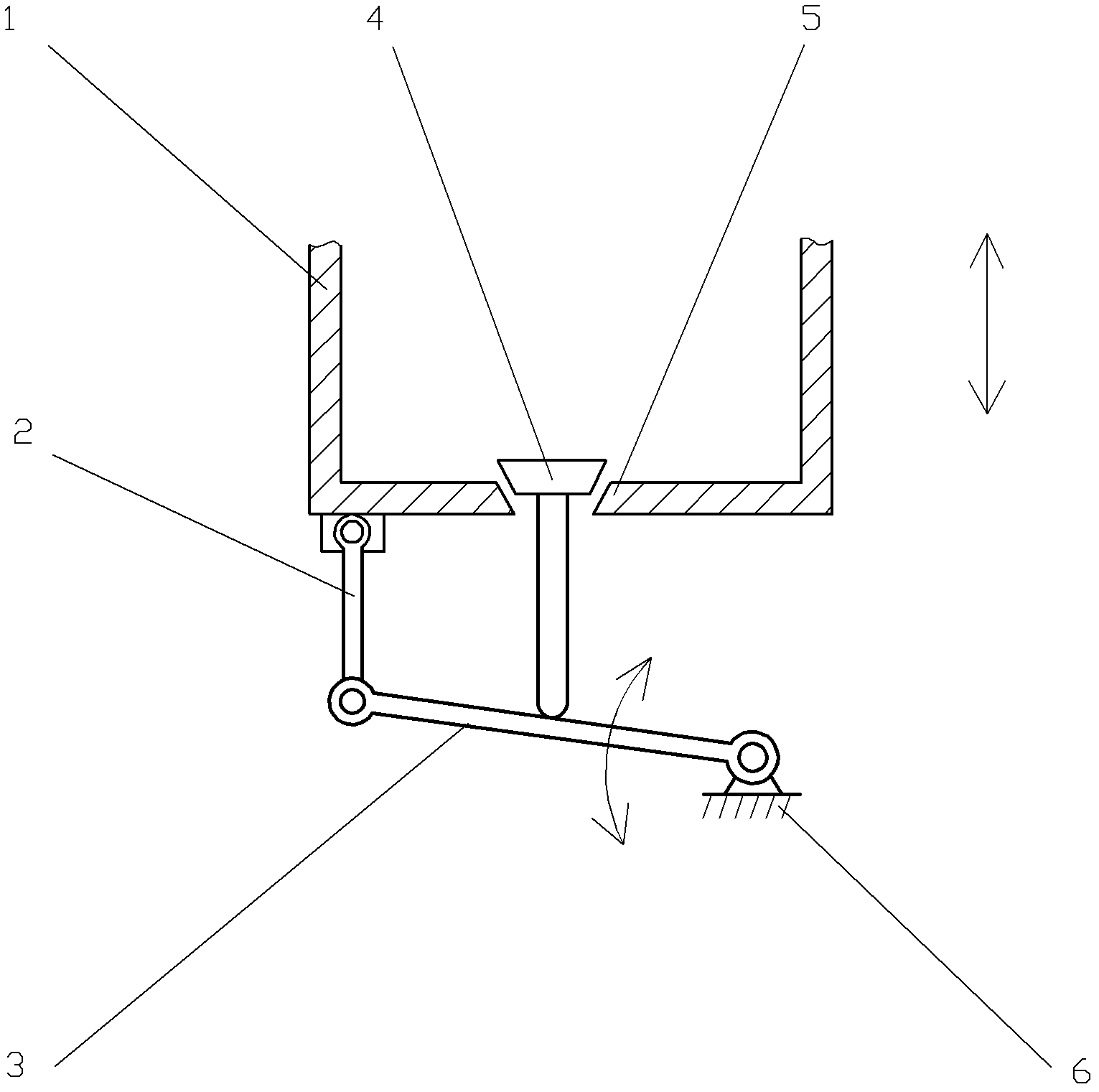
[0049] Such as figure 1 The air distribution mechanism of the reciprocating body shown, the gas distribution mechanism of the reciprocating body includes a reciprocating body 1, a swing rod 3 and a valve 4, a valve seat 5 is set on the reciprocating body 1, and the distribution The air valve 4 is arranged on the air distribution seat opening 5 , and the air distribution valve 4 cooperates with the air distribution seat opening 5 . The gas distribution mechanism of the reciprocating body further includes a connecting rod 2, one end of the connecting rod 2 is rotatably connected to the reciprocating body 1, and the other end of the connecting rod 2 is rotatably connected to one end of the swing rod 3, The other end of the swing rod 3 is rotatably connected with the machine body 6 . The swing rod (3) swings under the action of the reciprocating body (1). The valve valve 4 is acted by the swing rod 3 to open or close the valve seat port 5 according to the timing relationship. ...
Embodiment 2
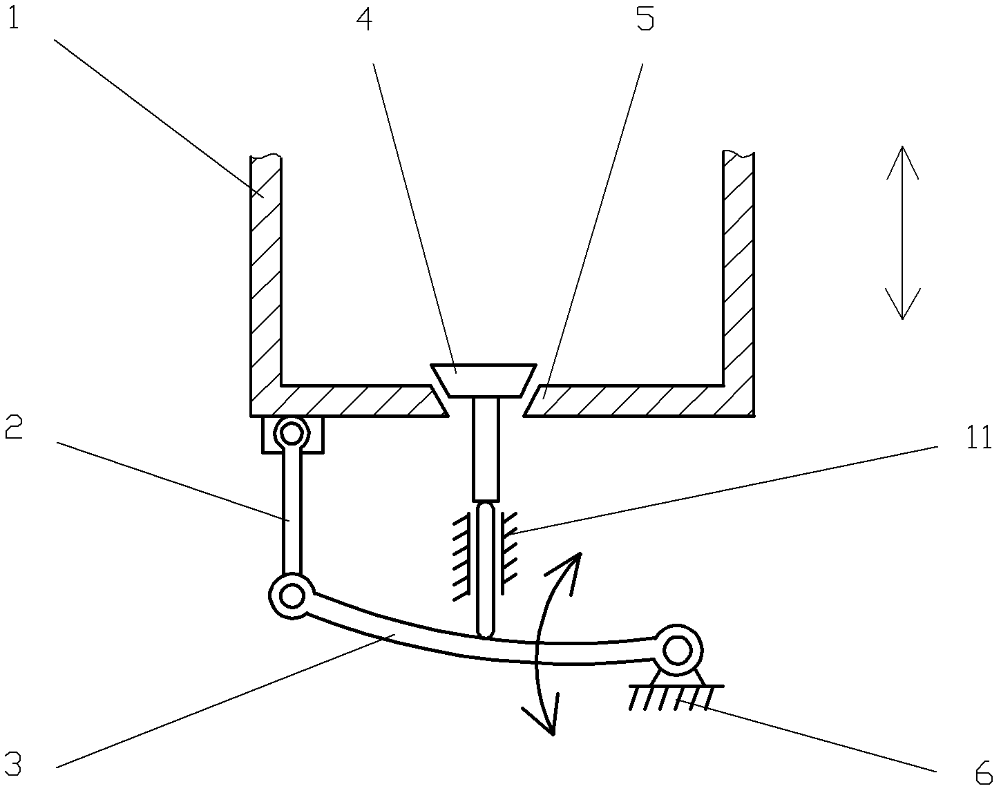
[0053] Such as figure 2 The difference between the shown reciprocating body gas distribution mechanism and Embodiment 1 is that a guide sliding structure 11 is provided between the valve 4 and the swing rod 3 . The function of the guide sliding structure 11 is to reduce the lateral displacement during the opening and closing process of the valve 4, so that the opening and closing process is more stable and reliable.
Embodiment 3
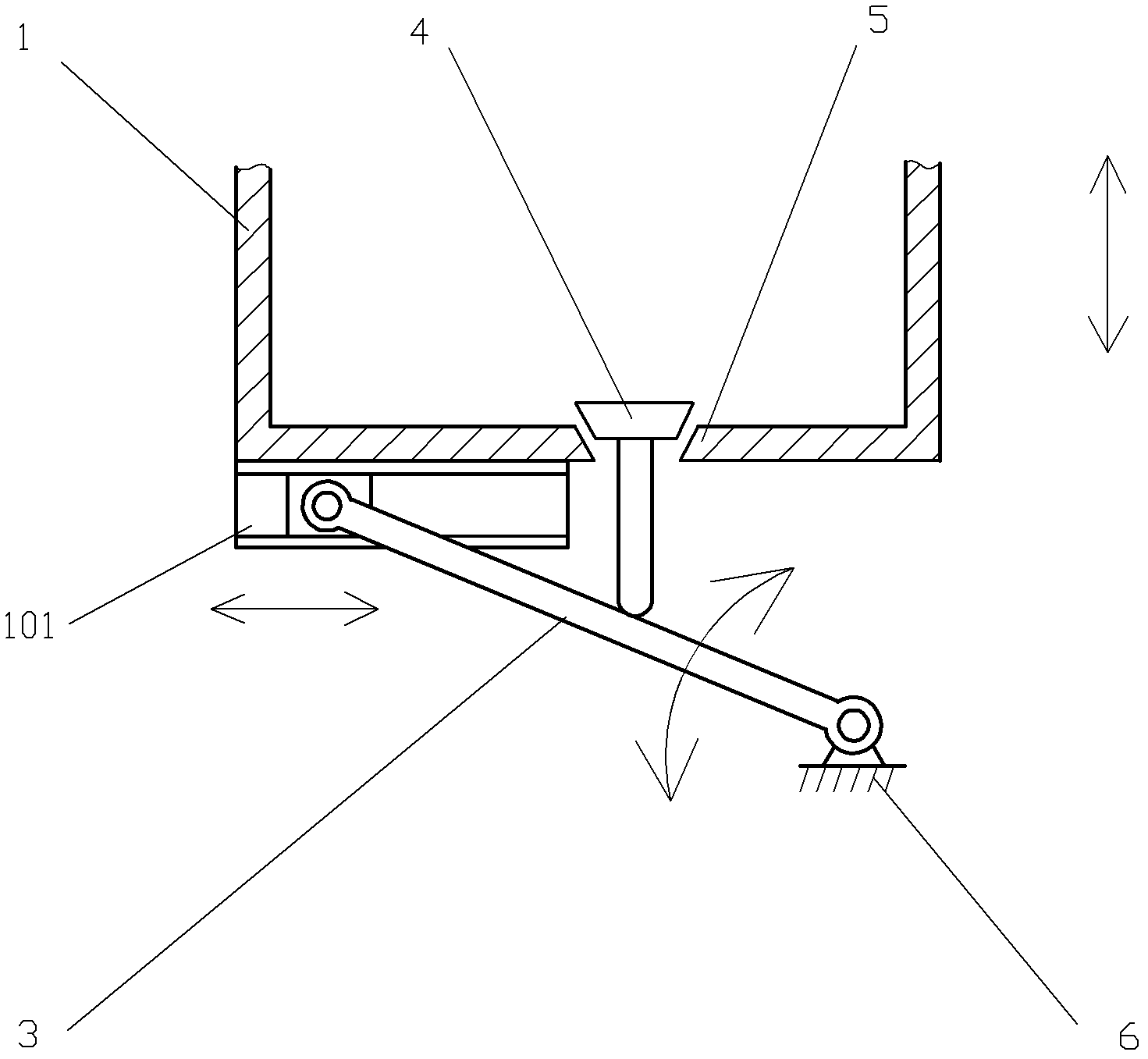
[0055] Such as image 3 The difference between the shown reciprocating body gas distribution mechanism and Embodiment 1 is that a slideway 101 is provided on the reciprocating body 1 to replace the connecting rod 2 in Embodiment 1. One end of the swing rod 3 is slidingly matched with the slideway 101 , and the other end of the swing rod 3 is connected to the machine body 6 in rotation.
PUM
 Abstract
Description
Claims
Application Information
 - R&D
- Intellectual Property
- Life Sciences
- Materials
- Tech Scout
- Unparalleled Data Quality
- Higher Quality Content
- 60% Fewer Hallucinations
Browse by: Latest US Patents, China's latest patents, Technical Efficacy Thesaurus, Application Domain, Technology Topic, Popular Technical Reports.
© 2025 PatSnap. All rights reserved.Legal|Privacy policy|Modern Slavery Act Transparency Statement|Sitemap|About US| Contact US: help@patsnap.com


