Microscopic flap lifting device used in LASIK (laser-assisted in situ keratomileusis) operation for femtosecond flap making

A femtosecond manufacturing and inlay technology, which is applied in the field of medical devices, can solve the problems of undiscovered patent documents, affecting postoperative vision, and prone to micro-wrinkles, etc., to facilitate excimer laser cutting, reduce damage, and completely separate Effect

Inactive Publication Date: 2013-12-04
王雁 +2
View PDF5 Cites 0 Cited by
  • Summary
  • Abstract
  • Description
  • Claims
  • Application Information

AI Technical Summary

Problems solved by technology

However, the thinner corneal flap makes it more difficult to lift the flap. The thinner corneal flap is prone to microfolds after surgery, which affects postoperative vision. For this reason, the width of the pedicle can be appropriately increased, but at the same time, it is necessary to prepare for the next step of excimer laser ablation. Provides sufficient optic zone, thus requires sufficient separation of the peripheral corneal flap below the pedicle
[0003] Through searching, no published patent documents related to this patent application have been found

Method used


Image

  • Microscopic flap lifting device used in LASIK (laser-assisted in situ keratomileusis) operation for femtosecond flap making
  • Microscopic flap lifting device used in LASIK (laser-assisted in situ keratomileusis) operation for femtosecond flap making
  • Microscopic flap lifting device used in LASIK (laser-assisted in situ keratomileusis) operation for femtosecond flap making

Examples


Embodiment 1

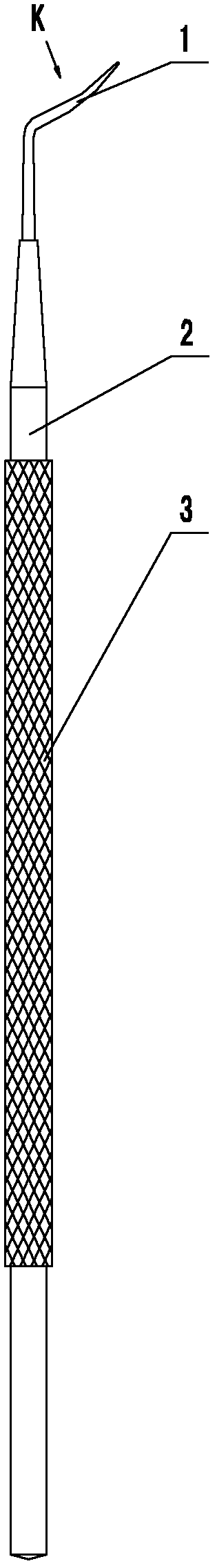
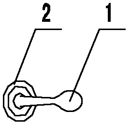
[0024] A micro flap lifter for femtosecond flap LASIK surgery, such as figure 1 , 2 As shown, it consists of a flap part 1 and a handle 2. The flap part is fixed on the upper end of the handle, and an anti-slip pattern 3 is formed on the hand-held part of the handle to prevent slippage of the instrument during the operation and make the operation safer.

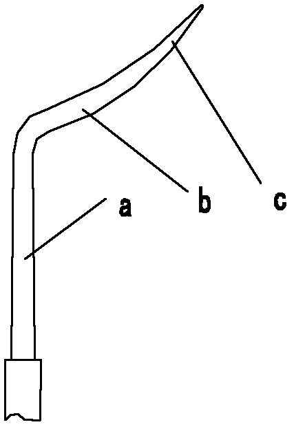
[0025] The structure of flap part is as image 3 , 4 , 5, the flap part is integrally connected by straight bar section a, arc section b and flat shovel section c, wherein the lower end of the straight bar section is coaxially fixed with the upper end of the handle, or is made in one body, and its horizontal The section is circular; with the extension of the upper part of the straight rod section, the diameter of the section becomes smaller gradually, and turns after about 1.5 cm, forming a circular arc section with an obtuse angle with the straight rod section. The cross section of the circular arc section is Flat ellipse...

Embodiment 2

[0030] A micro flap lifter for femtosecond flap LASIK surgery, see Figure 6 , 7 , 8, 9. Its external structure also includes a handle and a flap part, and the structure of the flap part in this embodiment is different from that in Embodiment 1. Only the structure of the flap portion is described below:

[0031] Such as Figure 6 As shown, the flap part includes a straight rod segment, an arc segment and a flat shovel segment, but there is also a turning segment d between the straight rod segment and the arc segment, and the turning segment and the straight rod segment are bent at an obtuse angle; The turning section and the arc section are reverse turning at an acute angle.

[0032] For the cross-sectional shapes of the straight bar section, between the turning section and the arc section, and the arc section, refer to Figure 9 , Figure 8 , Figure 7 .. The specific structure is described as follows:

[0033] The straight rod section is the direct continuation or f...


PUM


Abstract

The invention relates to a microscopic flap lifting device used in LASIK (laser-assisted in situ keratomileusis) operation for femtosecond flap making, comprising a flap lifting part and a handle, wherein the flap lifting part is fixedly arranged on the upper end of the handle; the flap lifting part includes a straight rod section, an arc section and a flat spade section which are manufactured integrally and connectedly; the lower end of the straight rod section is coaxially connected with the upper end of the handle, the upper blunt angle turning of the straight rod section is connected with the arc section, the section diameter and conical degree of the arc section become smaller gradually, the terminal end of the arc section is connected with the flat spade section with oval tips, and the cross section of the flat spade section is centrally thick and peripherally thin in shape. The microscopic flap lifting device disclosed by the invention can thoroughly separate corneal stroma flaps and reduce corneal flap damage, corneal flap dissociation and other complications during separation process, and is helpful for completely lifting the flap; meanwhile, the oval flat chisel section can reduce separation difficulty caused by opaque bubble layer (OBL) and reduce the damage on corneal tissue caused by repeated operation, and is helpful for post-operative wound recovery.

Description

technical field [0001] The invention belongs to the field of medical instruments, and relates to microsurgical instruments related to corneal refractive surgery, in particular to a microscopic flap lifter for femtosecond flap-making LASIK surgery. Background technique [0002] Excimer laser in situ keratomileusis (laser in situ keratomileusis, LASIK) is currently the mainstream of corneal refractive surgery, and its safety and effectiveness have gradually been widely recognized by the majority of patients with refractive errors. The production of the corneal flap is one of the key steps. At present, the microkeratome is widely used to complete the production of the corneal flap, but it has a relatively high risk, and some serious complications related to the flap are prone to occur, such as incomplete flap, broken flap, free flap, etc. Flaps, button flaps, etc., have seriously affected the operation and the recovery of postoperative vision, resulting in a decline in visual q...

Claims


Application Information

Patent Timeline
Patent Type & Authority Patents(China)
IPC IPC(8): A61F9/01
Inventor 王雁鲍锡柳张哲左彤
Owner 王雁
Why Eureka
Try Eureka