
Ammonia production process

A technology of ammonia synthesis and ammonia synthesis, which is applied in the field of ammonia preparation, can solve the problems of reducing overall efficiency and accumulation of inert gas, and achieve the effect of increasing load and energy consumption

Inactive Publication Date: 2012-07-18
AMMONIA CASALE SA
View PDF6 Cites 10 Cited by
  • Summary
  • Abstract
  • Description
  • Claims
  • Application Information

AI Technical Summary

Problems solved by technology

[0004] It is also known that a certain amount of purge gas flow is taken from the HP loop to remove inert gases, otherwise, the inert gases may build up and reduce the overall efficiency

Method used


Image

  • Ammonia production process
  • Ammonia production process
  • Ammonia production process

Examples


no. 1 approach

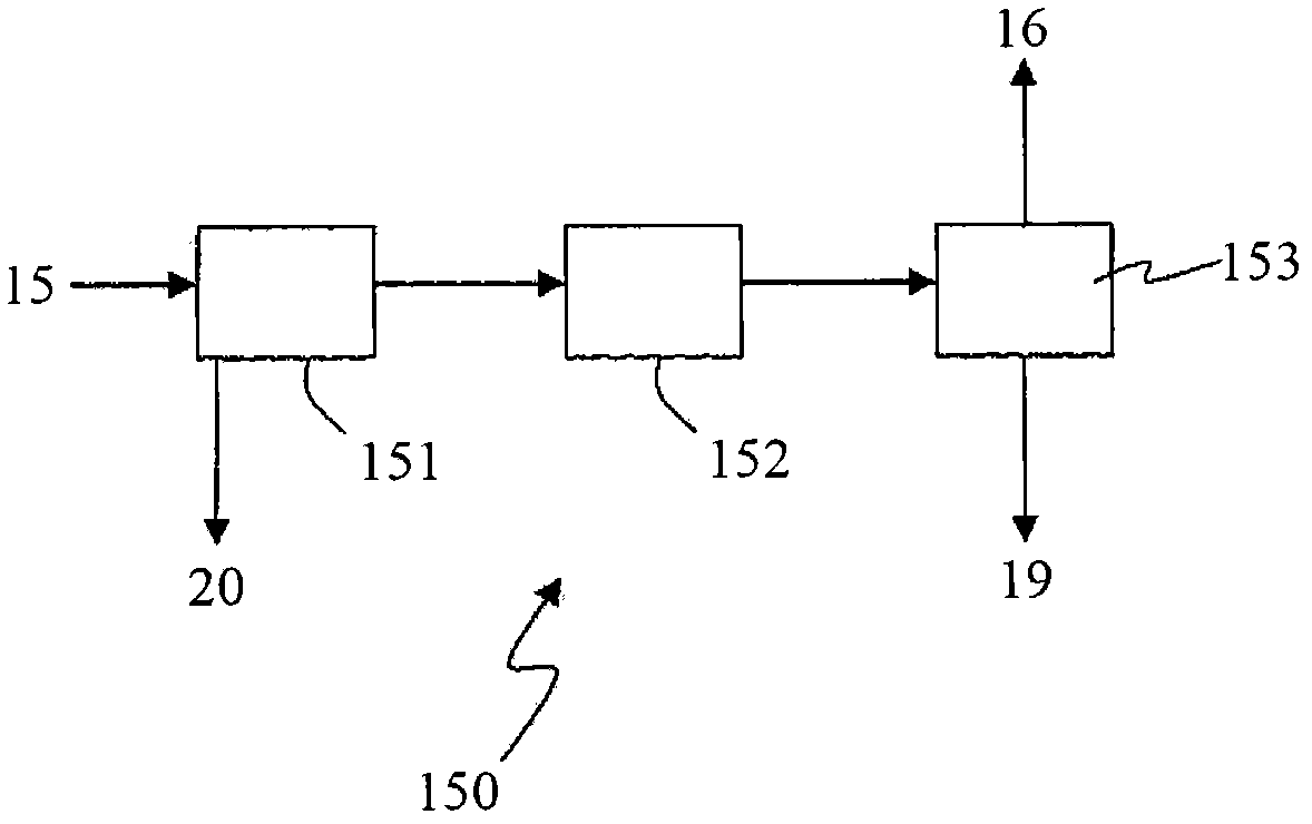
[0052] According to a first embodiment, the hydrogen separation frame includes TSA molecular sieves or PSA molecular sieves. According to a second embodiment, the hydrogen separation frame comprises a cryogenic separator. A water removal section 152 must be provided with a cryogenic separator.

[0053] The off-gas 19 may be recycled directly as fuel to the primary reformer 101 or used to regenerate the water removal section 152 before being recycled as fuel in said primary reformer 101 .

[0054] For example, the primary reformer 101 is equipped with catalytic tubes. In a preferred embodiment, the operating pressure in the catalytic tubes is greater than 35 bar; preferably 40 to 100 bar, and more preferably 60 to 80 bar.

[0055] The present invention achieves the objects and purposes set forth above. Due to the circulation of hydrogen by means of stream 15, stream 16 and stream 17, the energy consumption of the circulator 140 is slightly increased, which is well compensate...


PUM


Abstract

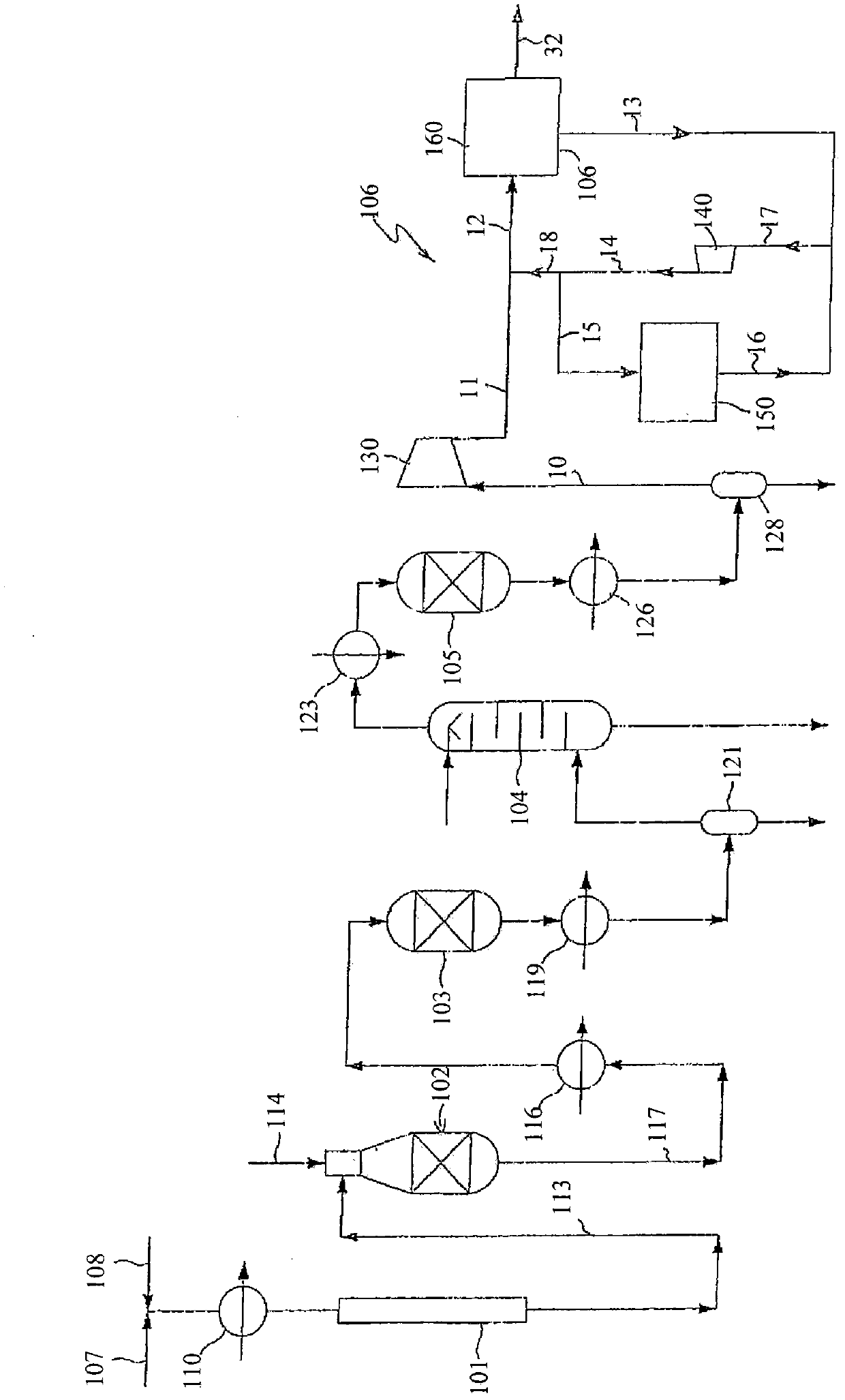
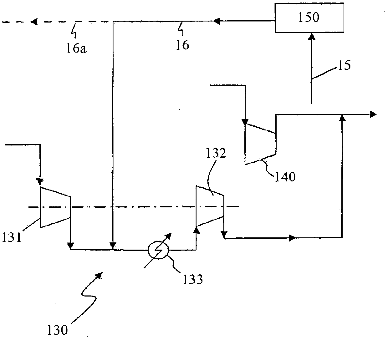
A process for the synthesis of ammonia, where: a front-end produces a make-up syngas (10) having a substantial excess of nitrogen, the H2 / N2 ratio being less than 3; hydrogen is separated from a purge stream (15) taken in the high-pressure synthesis loop, with a molecular sieve or a cryogenic device, obtaining a hydrogen-rich gaseous stream (16); said hydrogen-rich gaseous stream (16) is returned to the ammonia synthesis loop, thus obtaining that the H2 / N2 ratio of the gas feed (12) actually converted into ammonia is close to 3 and preferably in the range 2.9 - 3.1.

Description

technical field [0001] The invention relates to a process for the preparation of ammonia. More specifically, the present invention relates to a process for the production of ammonia by catalytic reaction of make-up synthesis gas in a high-pressure synthesis loop, and said make-up synthesis gas is produced by conversion of hydrocarbon feedstocks. Background technique [0002] Known methods of producing ammonia involve the catalytic reaction of make-up synthesis gas comprising hydrogen and nitrogen in a high-pressure (HP) synthesis loop typically operating at a pressure of about 80 to 300 bar. The make-up synthesis gas is produced in the upstream front end of the synthesis loop by converting a suitable hydrocarbon feedstock, eg natural gas. For example, at a temperature of about 800°C, hydrocarbon feedstocks are desulfurized and subsequently steam reformed in a reformer to obtain 2 and H 2 The first gas product; at a temperature of about 1 000 ° C, the first gas product is ...

Claims


Application Information

Patent Timeline
Patent Type & Authority Applications(China)
IPC IPC(8): C01C1/04
CPCC01C1/0476C01C1/0482Y02P20/129Y02P20/52
Inventor 马西莫·埃尔勃
Owner AMMONIA CASALE SA
Learn More