
Stepless variable power inductive ballast

A variable power and inductive technology, applied in the field of stepless variable power inductive ballasts, can solve problems such as over-power operation, arcing, power failure, etc., to reduce maintenance costs, maintain consistent operating characteristics, and increase operating current Effect

Inactive Publication Date: 2012-07-18
WUXI AINUOTAI ENERGY TECH
View PDF5 Cites 2 Cited by
  • Summary
  • Abstract
  • Description
  • Claims
  • Application Information

AI Technical Summary

Problems solved by technology

[0007] (2) The control method is to switch the taps of the inductance coil regularly through the timer. The control method is open-loop, and there are instantaneous power failure and arcing at the moment of switching.
[0008] (3) The high-voltage discharge lamp circuit composed of preset variable power inductive ballasts belongs to graded work. It is the same as the basic ballast (fixed inductive ballast) in the basic off work, and the external high voltage will make the The phenomenon of over-power operation of the high-pressure gas discharge lamp has no effect on prolonging the service life of the lamp tube
[0010] (5) Its basic section is equivalent to a fixed inductive ballast. The phenomenon of discrete light-off caused by this section has not been changed, and the lamp tubes still need to be replaced sporadically, and the operation and maintenance costs are relatively high.

Method used


Image

  • Stepless variable power inductive ballast
  • Stepless variable power inductive ballast
  • Stepless variable power inductive ballast

Examples


Embodiment Construction

[0026] Below in conjunction with accompanying drawing, the present invention is described in detail.

[0027] In order to make the object, technical solution and advantages of the present invention clearer, the present invention will be further described in detail below in conjunction with the accompanying drawings and embodiments. It should be understood that the specific embodiments described here are only used to explain the present invention, not to limit the present invention.

[0028] Such as Figure 5 As shown, it is a functional block diagram of a high pressure discharge lamp circuit composed of a stepless variable power ballast of the present invention. A steplessly variable power inductive ballast, the steplessly variable power inductive ballast is set between a high-pressure discharge lamp (load) 1 and a power supply (or called a mains power grid), and the steplessly variable power The inductive ballast is mainly composed of a constant power control device, a step...


PUM


Abstract

The invention discloses a stepless variable power inductive ballast which is arranged between a load and a power supply, and comprises a constant power control device, a stepless varindor and a forward-reverse rotation motor; the constant power control device is used for acquiring load power, compares the load power with set power, outputs a control signal according to a comparison result, and thus drives the forward rotation and the number of rounds of forward rotation or the reverse rotation and the number of rounds of reverse rotation of the forward / reverse rotation motor; the stepless varindor comprises a fixed iron core and a moving iron core, and the move-in quantity of the moving iron core corresponding to the fixed iron core is adjusted through the forward / reverse rotation adjustment of a lead screw, so that the inductance which is output to the load is changed and the load power is controlled; the power input end of the forward / reverse rotation motor is electrically connected with the output end of the constant power control device; and a pin shaft (3) of the forward / reverse rotation motor is fixedly connected with the lead screw. The stepless variable power inductive ballast is linear and stepless, has no instantaneous power-off and arcing phenomena, and has the advantages that the service life of a lamp tube is prolonged, the energy-saving efficiency is improved and the maintenance cost is low.

Description

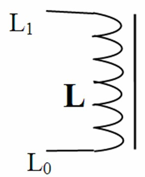
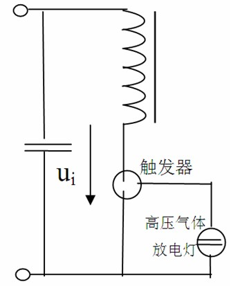
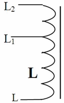
technical field [0001] The invention relates to an inductance ballast, in particular to a stepless variable power inductance ballast. Background technique [0002] Ballasts play an important role in lighting quality and lighting energy efficiency. Ballasts are divided into electronic ballasts and inductive ballasts. At present, inductive ballasts are mostly used in high-pressure gas discharge lamps. [0003] There are two technologies for ballasts used in high-pressure gas discharge lamps. The fixed inductive ballasts were used in the early stage. The principle is as follows: figure 1 As shown, it is equivalent to an inductor with a fixed value, and the equivalent circuit applied to the circuit of the high-pressure gas lamp is as follows figure 2 As shown; the inductance of this ballast cannot be adjusted, so the brightness and power of the high-pressure gas discharge lamp cannot be adjusted, and it cannot meet the requirements of low-carbon, energy-saving, and environmen...

Claims


Application Information

Patent Timeline
Patent Type & Authority Applications(China)
IPC IPC(8): H05B41/36
Inventor 张建平王新民
Owner WUXI AINUOTAI ENERGY TECH
Learn More