Multilayer channel member of ultrasonic fluid measuring device and ultrasonic fluid measuring device
A technology for fluid measurement and flow path measurement, which is applied in the direction of measurement devices, liquid/fluid solid measurement, flow measurement/mass flow measurement, etc., to achieve the effect of enhancing measurement accuracy
- Summary
- Abstract
- Description
- Claims
- Application Information
AI Technical Summary
Problems solved by technology
Method used
Image

Examples
no. 1 example
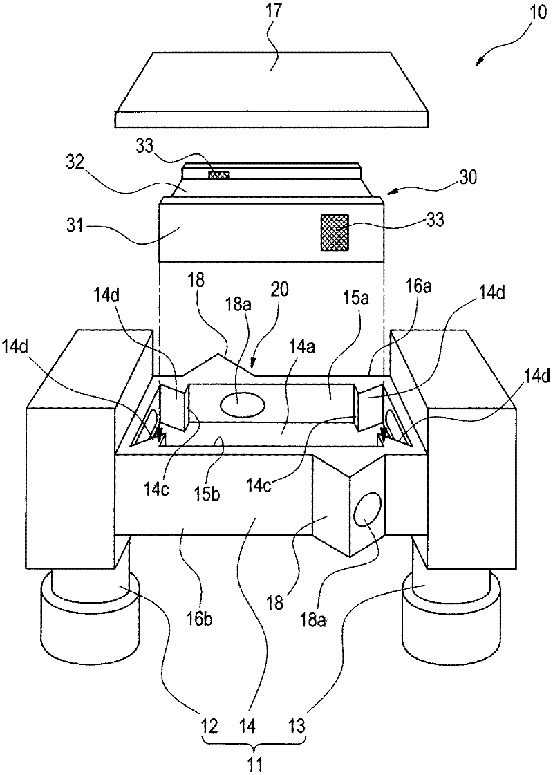
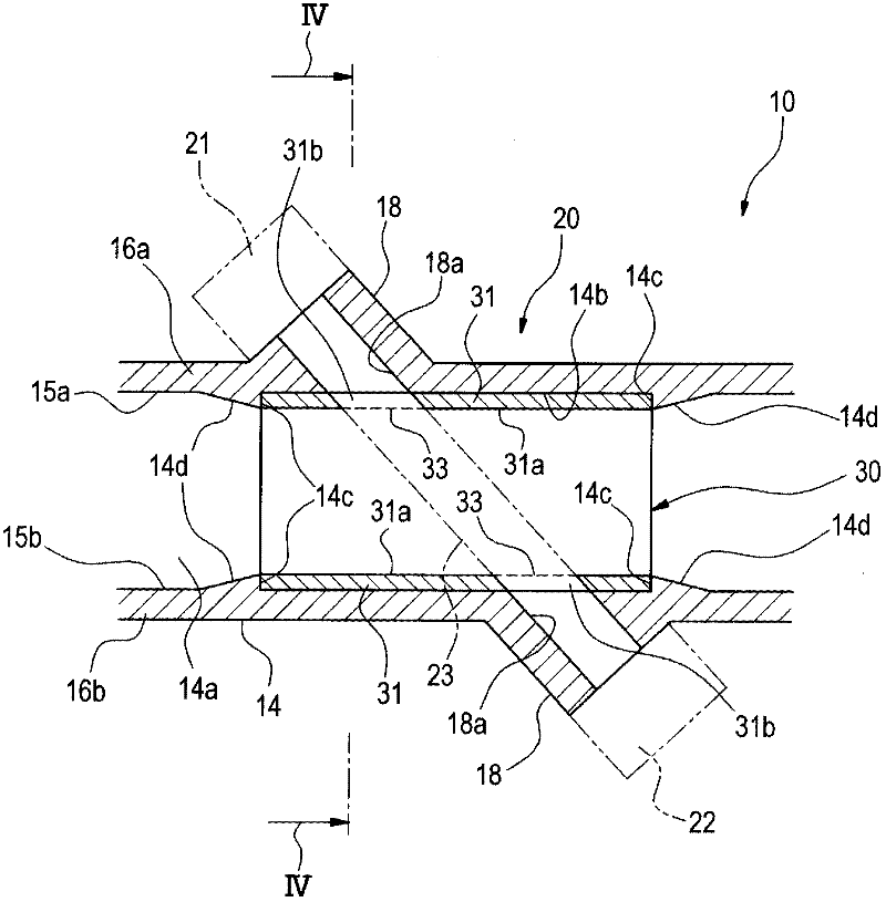
[0182] Such as figure 1 As shown in the figure, the ultrasonic fluid measuring device 10 according to the first embodiment has a fluid path 11 formed substantially in an inverted U shape, which consists of vertical flow paths 12 and 13 on the left and right sides and a vertical flow path connecting the left and right sides. The upper end portions of the flow paths 12 and 13 are constituted by a horizontal flow path 14. The horizontal flow path 14 has a measurement flow path 14a for measuring fluid, and in the measurement flow path 14a, a first transceiver (here, a transmitter) 21 and a second transceiver (here, a receiver) The ultrasonic measuring part 20 of 22 is provided on a pair of opposed inner faces 15a and 15b. In addition, the measurement flow path 14a has: a multilayer flow path member 30 for dividing the fluid into a plurality of flat flow paths; and a cover 17 for accommodating the multilayer flow path member 30 in the measurement flow path 14a, And used for sealing...
no. 2 example
[0196] Next, the ultrasonic fluid measuring device and the multilayer flow path member of the ultrasonic fluid measuring device according to the second embodiment of the present invention will be described.
[0197] Figure 5 Is a perspective view of the multilayer flow path member according to the second embodiment, and Image 6 It is a cross-sectional view of the multilayer flow path member according to the second embodiment. The same parts as those of the ultrasonic fluid measuring device and the multilayer flow path member of the ultrasonic fluid measuring device according to the first embodiment described above are denoted by the same reference numerals, and will not be discussed again.
[0198] Such as Figure 5 with Image 6 As shown, the multilayer flow path member 30B according to the second embodiment has extension portions 34 provided at the end of the frame 31B along the flow direction, and the inner side surface 34a of each extension portion 34 and the inner surface of ...
no. 3 example
[0200] Next, the ultrasonic fluid measuring device and the multilayer flow path member of the ultrasonic fluid measuring device according to the third embodiment will be described.
[0201] Figure 7 Is a perspective view of a multilayer flow path member according to the third embodiment, and Figure 8 It is an exploded perspective view of the main part of the ultrasonic fluid measuring device according to the third embodiment. The same parts as those of the ultrasonic fluid measuring device and the multilayer flow path member of the ultrasonic fluid measuring device according to the first and second embodiments described above are denoted by the same reference numerals and will not be described again. discuss.
[0202] Such as Figure 7 with Figure 8 As shown, the multilayer flow path member 30C according to the third embodiment is provided with a bottom 35 in the lower ends of the frames 31B and 31B described in the second embodiment, and the cross section is formed in a U-shape...
PUM
 Abstract
Description
Claims
Application Information
 - R&D
- Intellectual Property
- Life Sciences
- Materials
- Tech Scout
- Unparalleled Data Quality
- Higher Quality Content
- 60% Fewer Hallucinations
Browse by: Latest US Patents, China's latest patents, Technical Efficacy Thesaurus, Application Domain, Technology Topic, Popular Technical Reports.
© 2025 PatSnap. All rights reserved.Legal|Privacy policy|Modern Slavery Act Transparency Statement|Sitemap|About US| Contact US: help@patsnap.com