Variable-diameter columnar type gas pressure spring
A gas spring and cylinder technology, applied in the field of spring manufacturing, can solve the problems of insufficient gas spring deformation stroke, complex production process of parts, complex structure, etc., to overcome the problems of easy corrosion and non-adjustable elastic force, save transportation costs, and overcome the problems of complex structure Effect
- Summary
- Abstract
- Description
- Claims
- Application Information
AI Technical Summary
Problems solved by technology
Method used
Image
Examples
Embodiment 1
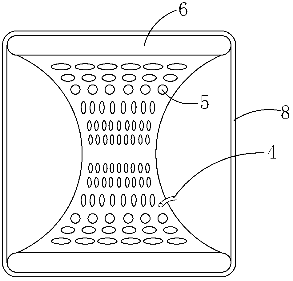
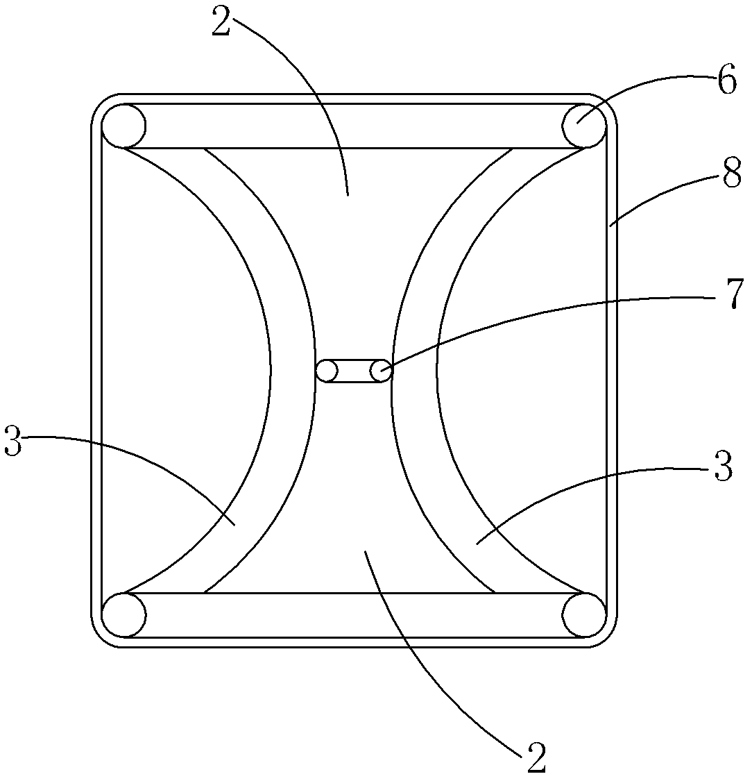
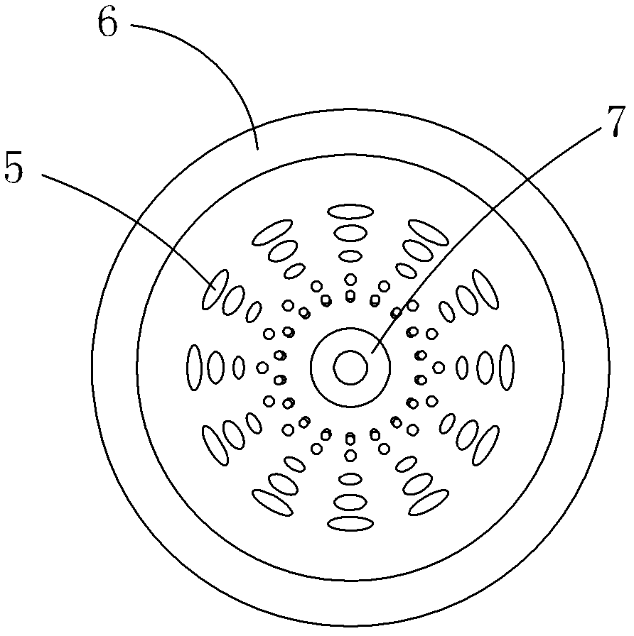
[0021] Embodiment 1: as figure 1 and 2 A variable-diameter cylindrical gas spring shown includes a spring body 1. The spring body 1 is formed by at least one hollow cavity 2. The side wall of the cavity 2 is a double-layer structure. A sealed chamber 3 for containing pressure gas is formed. The chamber 2 is in the shape of a variable-diameter cylinder with thick ends and a thin middle, and each chamber 3 is provided with vent holes 4; the side wall of the chamber 2 is provided with several rows The ventilation holes 5 (such as image 3 shown); the air holes 5 near the two ends of the cavity 2 are horizontal waist-shaped holes, and the air holes 5 of each row gradually become vertical waist-shaped holes as they are arranged in the middle of the cavity 2; the upper and lower openings of the cavity 2 All of them are lined with recoverable deformable setting rings 6, and the small diameter of the inner wall of the cavity 2 is lined with a reinforcing ring 7 parallel to the setti...
Embodiment 2
[0024] Embodiment 2: The difference between this embodiment and the previous embodiment 1 is that the side wall of the cavity 2 has three layers, which will form stacked double-layer chambers 3. In actual use, the inflation of each chamber 3 can be individually adjusted Increase the elastic adjustment range. For example: when not in use, neither of the double chambers 3 is inflated; when the elastic force is required to be small, one chamber 3 can be inflated separately; when the elastic force is required to be large, the two chambers 3 can be inflated at the same time. And the inflation volume of each chamber 3 can be adjusted according to the actual situation, so as to realize a large stepless adjustment of the elastic force.
[0025] If any one layer of side walls is damaged and leaks air, the remaining two layers of side walls can still be retained or fused to form an independent chamber 3, which improves the service life of the present invention.
Embodiment 3
[0026] Embodiment 3: The difference between this embodiment and the preceding embodiments 1 and 2 is that the cross-section of the cavity 2 can be changed to a polygon according to the usage conditions. When the cavity 2 has a polygonal cross-section (such as Figure 6 As shown), the setting rings 6 on the upper and lower sides of the cavity 2 and the reinforcing ring 7 in the middle are also polygonal in shape, but the vertical section of the cavity 2 is still a concave drum shape with a smooth arc surface to ensure the compressive strength.
PUM
 Abstract
Description
Claims
Application Information
 - R&D
- Intellectual Property
- Life Sciences
- Materials
- Tech Scout
- Unparalleled Data Quality
- Higher Quality Content
- 60% Fewer Hallucinations
Browse by: Latest US Patents, China's latest patents, Technical Efficacy Thesaurus, Application Domain, Technology Topic, Popular Technical Reports.
© 2025 PatSnap. All rights reserved.Legal|Privacy policy|Modern Slavery Act Transparency Statement|Sitemap|About US| Contact US: help@patsnap.com


