
Oil cylinder energy recovery and regeneration system

An energy recovery and regeneration system technology, which is applied in fluid pressure actuation system components, fluid pressure actuation devices, mechanical equipment, etc., can solve problems such as rising oil temperature, reducing the life of hydraulic components, and energy waste, so as to improve oil return Effect of pressure, reduced flow, prolonged time

Inactive Publication Date: 2012-07-18
SANY HEAVY MACHINERY
View PDF5 Cites 15 Cited by
  • Summary
  • Abstract
  • Description
  • Claims
  • Application Information

AI Technical Summary

Problems solved by technology

[0003] The object of the present invention is an energy recovery and regeneration system for an excavator oil cylinder, to solve the energy waste caused by the lack of an energy recovery device in the current hydraulic excavator, and the conversion of the potential energy and kinetic energy of the boom into heat loss, which causes the oil temperature to rise and reduce the hydraulic pressure. Component life issues

Method used


Image

  • Oil cylinder energy recovery and regeneration system
  • Oil cylinder energy recovery and regeneration system

Examples


Embodiment approach

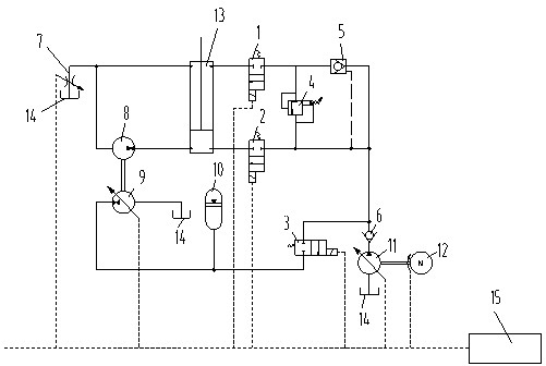
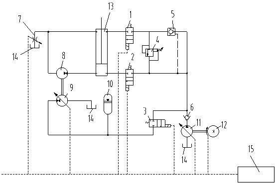
[0020] In the first embodiment of the present invention, please continue to refer to figure 1 shown. The above-mentioned second reversing valve 1 is connected with the first one-way valve 6 through a second one-way valve 5 .

[0021] In the second embodiment of the present invention, the second reversing valve 1 and the third reversing valve 2 are connected through an electromagnetic valve 4 . That is to say, one end of the first one-way valve 6 is connected with the accumulator 10 through the first reversing valve 3, and the other end of the first one-way valve 6 is divided into two paths, and one way passes through the third reversing valve 2 and connects with the hydraulic cylinder 13. The rod cavity is connected, and the other path is respectively connected with the rod cavity of the hydraulic cylinder 13 by connecting the second one-way valve 5 and the second reversing valve 1 in sequence.

[0022] In the third embodiment of the present invention, the connection between...


PUM


Abstract

The invention discloses an oil cylinder energy recovery and regeneration system, which comprises a hydraulic cylinder, an oil tank, a constant-displacement motor, an energy accumulator and an engine. One end of a rod-less cavity of the hydraulic cylinder is connected with one end of the constant-displacement motor, the other end of the constant-displacement motor is divided into two channels respectively connected with the oil tank and one end of a rod-end cavity of the hydraulic cylinder, a first variable-capacity pump is connected with the constant-displacement motor, one end of the first variable-capacity pump is connected with the oil tank, and the other end of the first variable-capacity pump is connected with the energy accumulator. A second variable-capacity pump is connected with the engine, one end of the second variable-capacity pump is connected with the oil tank, the other end of the second variable-capacity pump is connected with a first one-way valve, and the first one-way valve is connected with the energy accumulator through a first reversing valve. The other end of the rod-end cavity of the hydraulic cylinder is connected with the first one-way valve through a second reversing valve, the other end of the rod-less cavity of the hydraulic cylinder is connected with the first one-way valve through a third reversing valve. The oil cylinder energy recovery and regeneration system has the advantages that flow required for interlock of a movable arm is reduced effectively while time recovery time is prolonged effectively.

Description

technical field [0001] The invention relates to an energy recovery system, in particular to an energy recovery and regeneration system of an excavator oil cylinder. Background technique [0002] The hydraulic excavator is a typical periodic operation equipment, and the lowering of the boom is a typical part of its work cycle. When the boom of the hydraulic excavator is lowered, the current hydraulic excavator adjusts the lowering speed of the working arm through the opening of the main spool in the main valve, and stops the lowering movement of the boom by closing the main spool. Existing hydraulic excavators usually do not have an energy recovery device, and most of the potential energy released during the lowering of the boom is consumed on the main valve, resulting in a waste of energy. Moreover, during this process, the potential energy and kinetic energy of the boom are converted into heat loss, which also increases the oil temperature and reduces the life of the hydra...

Claims


Application Information

Patent Timeline
Patent Type & Authority Applications(China)
IPC IPC(8): F15B21/14
Inventor 韩涛汪春晖荆玉涛
Owner SANY HEAVY MACHINERY
Learn More