
ejector

A technology of injectors and actuators, which is applied in the direction of fuel injection devices, special fuel injection devices, machines/engines, etc. It can solve the problems of easily disturbed actuator movement and easily disturbed fuel volume, and achieves easy installation and less The effect of power loss

Inactive Publication Date: 2016-03-30
CONTINENTAL AUTOMOTIVE GMBH
View PDF8 Cites 0 Cited by
  • Summary
  • Abstract
  • Description
  • Claims
  • Application Information

AI Technical Summary

Problems solved by technology

[0004] Injectors usually have a large-area diaphragm which seals the actuator against the fuel, and the pressure in the low-pressure area is usually about 2.3 bar, since the control valve actuator of said injector protrudes into the low-pressure area, The movement of the actuator and thus the injected fuel quantity is therefore susceptible to disturbances due to the different pressure conditions in the low-pressure area, since a significant additional force acts partially on the actuator via the diaphragm surface

Method used


Image

  • ejector
  • ejector
  • ejector

Examples


Embodiment Construction

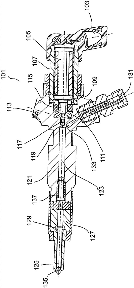
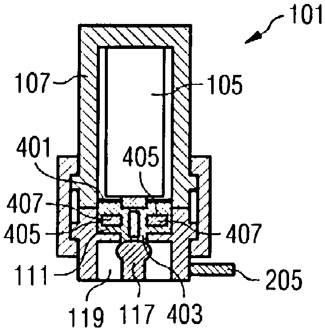
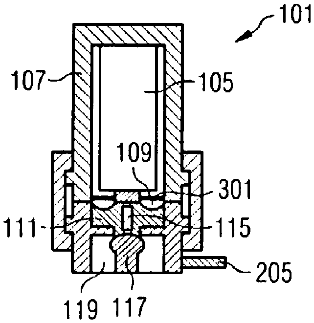
[0027] figure 1 Shown is a cross-sectional view of injector 101 of the present invention. The injector 101 includes an electrical connection 103 for supplying electrical power to a piezoelectric actuator 105 arranged in an actuator housing 107 . The actuator housing 107 is sealed in a fluid-tight manner with respect to the front chamber 111 by means of a double-walled membrane 109 . The antechamber 111 is placed in front of the fluid feedback pipeline (not shown) and is fluidly connected to it, so the antechamber 111 can also be referred to as the antechamber of the fluid feedback pipeline. The injector 101 also has a low pressure connection 113 to which a fluid return line is connected. The double-walled diaphragm 109 will be in image 3 be detailed in.

[0028] An actuator piston 115 is also arranged in the front chamber 111 , so that the extension of the piezo actuator 105 can be transmitted to a control valve 117 . Piezo actuator 105 is thus coupled via actuator pisto...


PUM


Abstract

The invention relates to an injector (101) having a control valve (117) for opening a control chamber (121) for controlling the nozzle needle position and an antechamber (111) of a fluid return line (205) The connection between them, wherein a pressure compensation mechanism is set in the front chamber (111), and the pressure compensation mechanism is used to compensate the change of the pressure in the front chamber.

Description

technical field [0001] The invention relates to an injector. Background technique [0002] Known injectors for injecting fuel into the combustion chamber of an internal combustion engine generally comprise a control valve for opening a connection between a control chamber for controlling the position of the nozzle needle and a prechamber of the fluid return line. [0003] Fuel intake by injection and switch leakage causes pressure fluctuations in the high and low pressure areas of the injector. [0004] Injectors usually have a large-area diaphragm which seals the actuator against the fuel, and the pressure in the low-pressure area is usually about 2.3 bar, since the control valve actuator of said injector protrudes into the low-pressure area, Due to the different pressure conditions in the low-pressure region, the movement of the actuator and thus the injected fuel quantity is susceptible to disturbances, since a significant additional force partially acts on the actuator ...

Claims


Application Information

Patent Timeline
Patent Type & Authority Patents(China)
IPC IPC(8): F02M47/02F02M61/16
CPCF02M47/02F02M47/027F02M2200/31F02M2200/315
Inventor U.容格G.马察恩W.赖辛格
Owner CONTINENTAL AUTOMOTIVE GMBH
Learn More