Vehicle power transmission device
a technology of transmission device and transmission device, which is applied in the direction of gearing details, gearing, transportation and packaging, etc., can solve the problems of noise and vibration, noise and vibration may easily occur, etc., and achieve the suppression of the generation of vibratory force, the reduction of the vibration force transmitted to the case, and the restraint of the reaction force of the meshing
- Summary
- Abstract
- Description
- Claims
- Application Information
AI Technical Summary
Benefits of technology
Problems solved by technology
Method used
Image
Examples
first embodiment
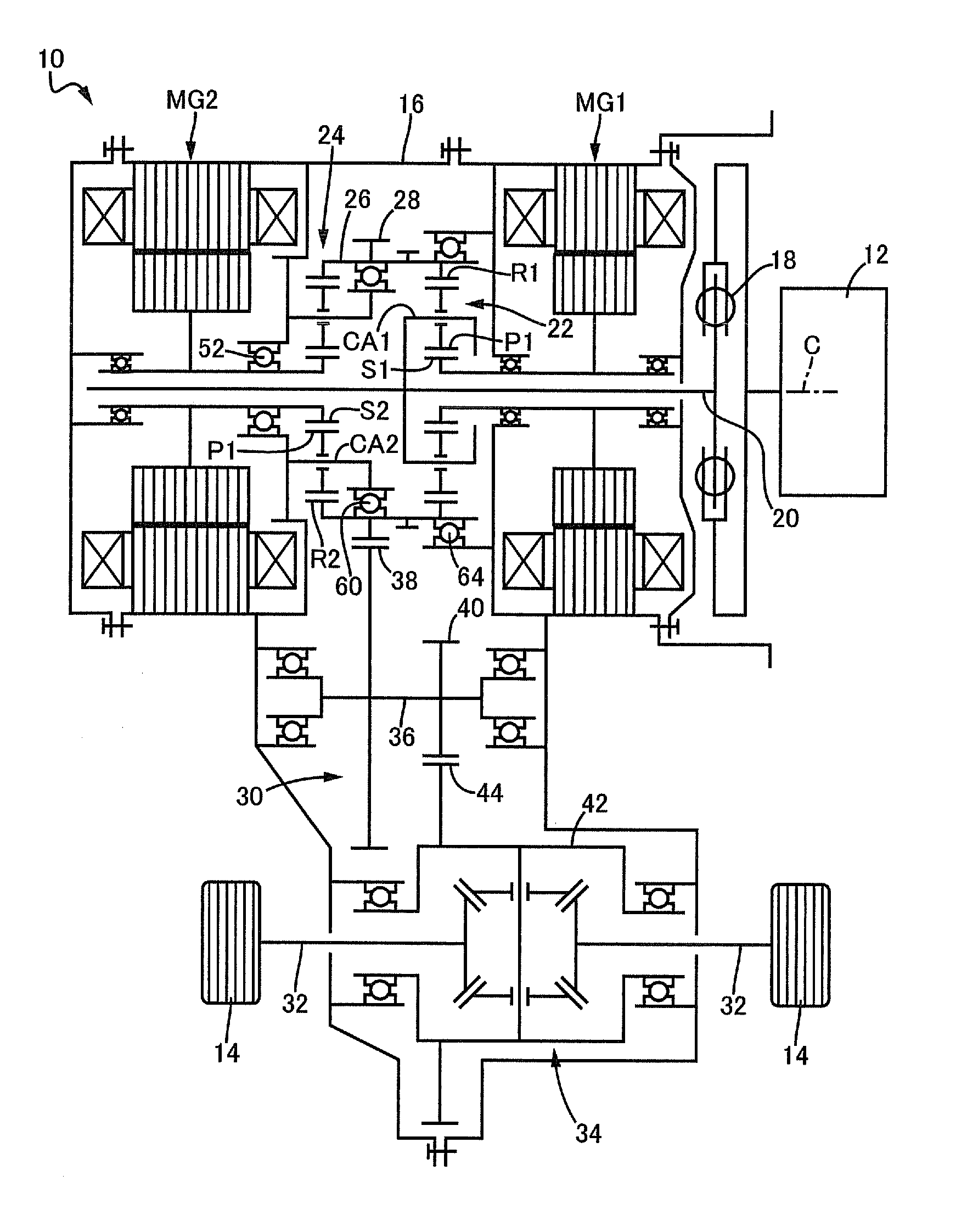
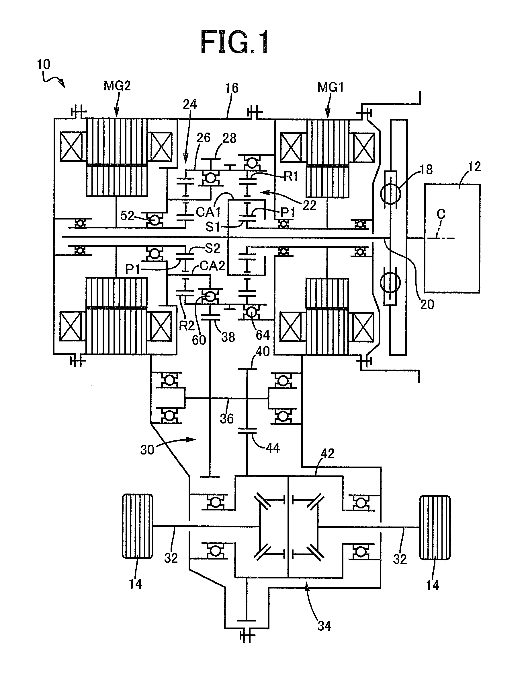
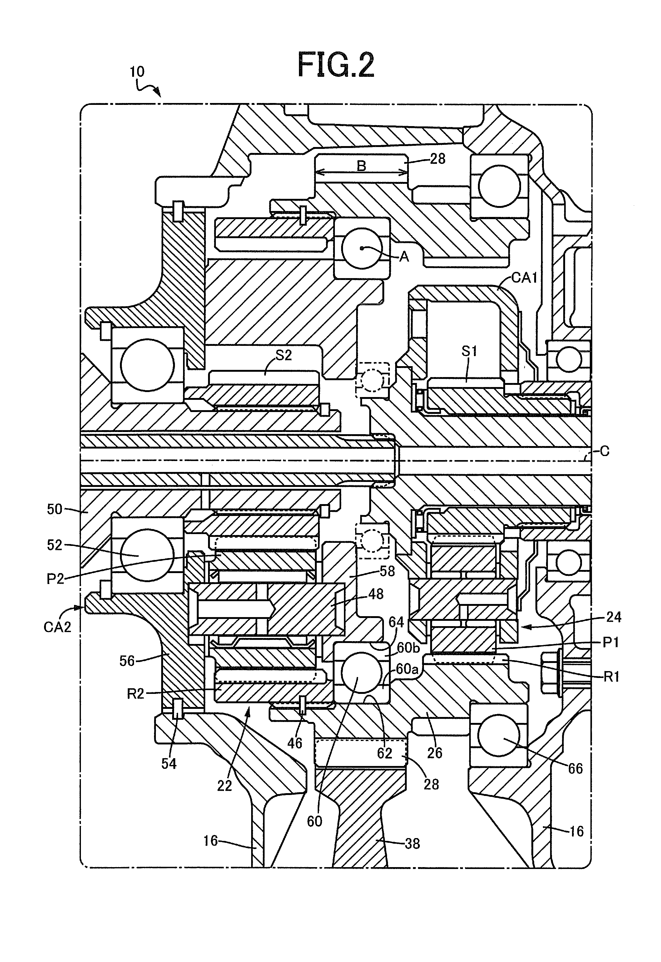
[0021]FIG. 1 is a schematic for explaining a configuration of a vehicle power transmission device 10 of one embodiment of the present invention. In FIG. 1, the power transmission device 10 is disposed on a power transmission path between an engine 12 and drive wheels 14 on a hybrid vehicle of the FF (front-engine front-drive) type, for example. The power transmission device 10 includes, in a transaxle case 16 attached to a vehicle body, a damper 18 absorbing pulsation due to fluctuations of torque from the engine 12, and an input shaft 20 coupled via the damper 18 to the engine 12, as well as a first motor generator MGI, a first planetary gear device 22, a second planetary gear device 24, and a second motor generator MG2 disposed in this order from the damper 18 side on the outer circumferential side of the input shaft 20. The transaxle case 16 corresponds to a case of the present invention. The first motor generator MGI corresponds to a first electric motor of the present invention...
second embodiment
[0042]Other embodiments of the present invention will be described. In the description of the following embodiments, the portions common to the embodiments are denoted by the same reference numerals and will not be described.
[0043]FIG. 3 is a cross-sectional view of a main portion of a vehicle power transmission device 70 of another embodiment of the present invention, corresponding to FIG. 2 of the first embodiment. As depicted in FIG. 3, in this embodiment, the second bearing 60 of the first embodiment is replaced with a second bearing 72 that is a cylindrical roller bearing. The second bearing 72 corresponds to the bearing of the present invention and is disposed between the first ring gear R1 and the second ring gear R2 on the inner circumferential side of a cylindrical output member 74 of this embodiment. The cylindrical output member 74 is rotatably supported by the second carrier member 58 of the second carrier CA2 fixed to the transaxle case 16, via the second bearing 72 dis...
third embodiment
[0051]FIG. 4 is a cross-sectional view of a main portion of a vehicle power transmission device 80 of another embodiment of the present invention, corresponding to FIG. 2 of the first embodiment. As depicted in FIG. 4, in this embodiment, the second bearing 60 of the first embodiment is replaced with a second bearing 82 that is a double row ball bearing. The second bearing 82 corresponds to the bearing of the present invention and is disposed between the first ring gear R1 and the second ring gear R2 on the inner circumferential side of a cylindrical output member 84 of this embodiment. The cylindrical output member 84 is rotatably supported by the second carrier member 58 of the second carrier CA2 fixed to the transaxie case 16, via the second bearing 82 disposed to entirely overlap with the first drive gear 28 when viewed in the direction orthogonal to the axial center line C on the inner circumferential side of the cylindrical output member 84.
[0052]The second bearing 82 is posit...
PUM
 Abstract
Description
Claims
Application Information
 - R&D
- Intellectual Property
- Life Sciences
- Materials
- Tech Scout
- Unparalleled Data Quality
- Higher Quality Content
- 60% Fewer Hallucinations
Browse by: Latest US Patents, China's latest patents, Technical Efficacy Thesaurus, Application Domain, Technology Topic, Popular Technical Reports.
© 2025 PatSnap. All rights reserved.Legal|Privacy policy|Modern Slavery Act Transparency Statement|Sitemap|About US| Contact US: help@patsnap.com


