
Side slope anchoring hole drilling construction equipment and side slope anchoring hole drilling construction method

A technology of construction equipment and drilling equipment, which is applied in the direction of drilling equipment and methods, drilling equipment, directional drilling, etc., which can solve the problems of high danger for construction personnel, long construction period, and large construction volume, so as to improve construction safety , improve work efficiency, simple construction method

Inactive Publication Date: 2012-07-18
SICHUAN UNIV
View PDF9 Cites 23 Cited by
  • Summary
  • Abstract
  • Description
  • Claims
  • Application Information

AI Technical Summary

Problems solved by technology

It can be seen that this construction method is difficult, the construction volume is large, the construction period is long, and the production cost is high.
More labor is required in the implementation of drilling operations, and the danger to construction personnel is also greater
In addition, if large-scale special equipment is used, such as using a long-arm work trolley, it is not only very expensive, but also has a limited working height, which cannot be used if it exceeds 20 meters.
Therefore, in the current slope anchoring construction, the drilling operation is labor-intensive and time-consuming, which has become a major problem affecting the progress and cost of the anchoring project.

Method used


Image

  • Side slope anchoring hole drilling construction equipment and side slope anchoring hole drilling construction method
  • Side slope anchoring hole drilling construction equipment and side slope anchoring hole drilling construction method
  • Side slope anchoring hole drilling construction equipment and side slope anchoring hole drilling construction method

Examples


Embodiment Construction

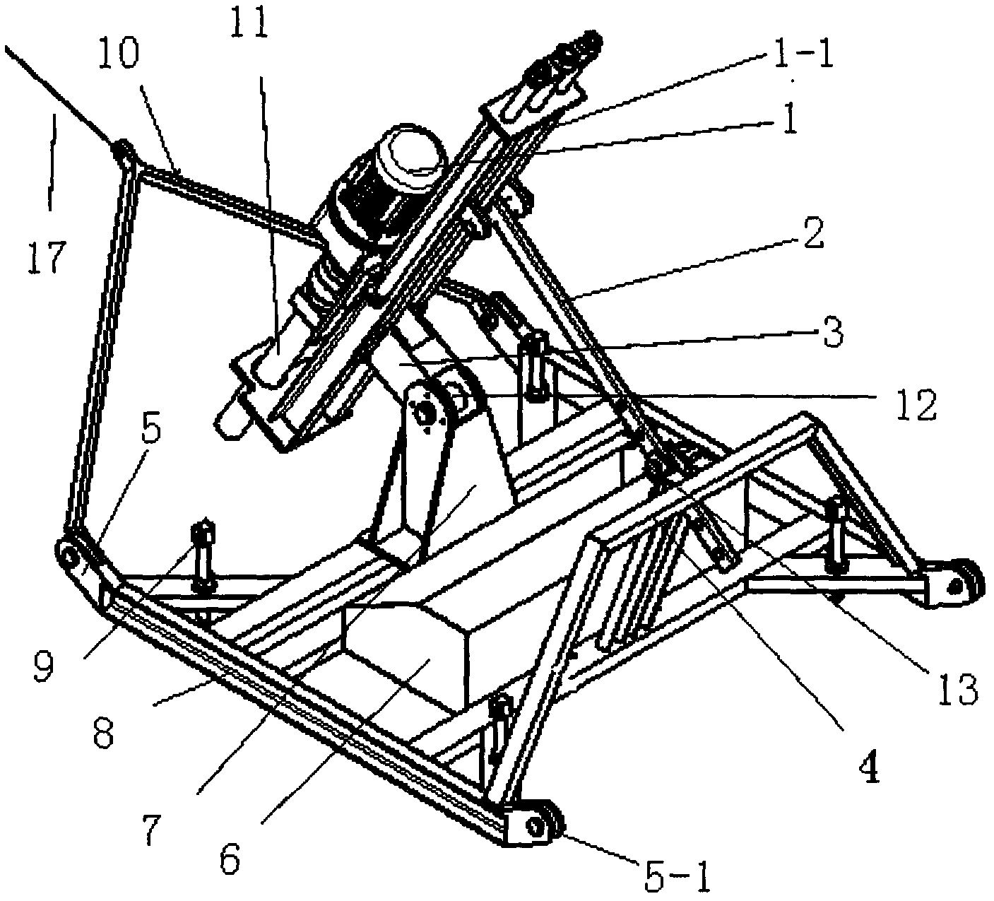
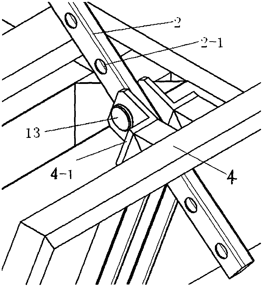
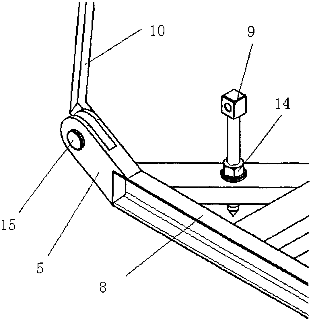
[0026] see figure 1 , figure 2 , the two front skid heads 5 of the front end of the sled frame 8 are hinged with the traction frame 10. One end of the steel cable 17 wound on the winch 16 is tied to the middle part of the traction frame 10 . The lower hinge base 7 is fixed on the middle front part of the frame 8, the upper hinge base 3 is fixed on the lower channel steel frame 1-1 of the drilling machine 1 with the drill rod 11, and the upper hinge base 3 and the lower hinge base 7 pass through the pins. The shaft 12 realizes the hinge connection. Back support 4 is fixed on the afterbody of frame 8. One end of the support rod 2 is supported on the rear portion of the drilling machine 1 channel steel frame in a hinged form. There is a support seat 4-1 containing a support hole 4-2 at the position relative to the support rod 2 on the rear bracket 4 at the rear of the frame, and the pin rod 3 is inserted into a certain positioning hole 2-1 of several positioning holes on the...


PUM


Abstract

The invention relates to side slope anchoring hole drilling construction equipment, which is used for geotechnical side slope anchoring engineering in road building and the like. The equipment comprises a drilling machine and a sledge type frame, two front sledge heads and two rear sledge heads are arranged at the front end and the rear end of the frame respectively, a traction frame is hinged onto the two front sledge heads of the frame, a lower hinged support is fixed to the middle front of the frame, and an upper hinged support fixed onto a channel steel frame of the drilling machine is hinged with the lower hinged support through pins. One end of a supporting rod is hinged to and abutted against the channel steel frame of the drilling machine while the other end of the supporting rod is provided with a plurality of positioning holes, a rear support is mounted at the rear end of the frame, a supporting seat is arranged on the rear support at a position corresponding to the supporting rod, the supporting seat is provided with a supporting hole, a pin rod penetrates through one of the positioning holes of the supporting rod and the supporting hole of the supporting seat to support the other end of the supporting rod on the supporting seat, and auxiliary cable ropes are tied to the front sledge heads and the rear sledge heads of the frame respectively. The equipment is portable in movement, labor intensity is relieved, and operating efficiency can be greatly improved. The invention further provides a side slope anchoring hole drilling construction method, which is laborsaving, timesaving, safe and reliable.

Description

Technical field: [0001] The invention belongs to the field of engineering such as road construction, and in particular relates to construction equipment and a construction method for slope anchorage drilling in rock and soil slope anchorage construction operations. Background technique: [0002] At present, in the construction of railways, highways and other projects in mountainous areas in China, anchoring technology is widely used to strengthen rock and soil slopes. Ordinary construction method often builds a platform with a scaffold bar before drilling anchor holes on the slope, and the platform is fixed with the anchor rod and the slope, and then the heavy drilling machine is lifted onto the platform. After drilling a hole, the drilling machine will be disassembled from the platform, and then the drilling machine will be manually moved along the scaffold to be installed and fixed on the next drilling position, and then the next hole will be drilled. The process not only...

Claims


Application Information

Patent Timeline
IPC IPC(8): E21B7/02E21B7/04E21B15/04
Inventor 魏星黄维菊
Owner SICHUAN UNIV
Learn More