Spile device of spile machine

The technology of a working device and a plug-in machine, which is applied in basic structure engineering, soil protection, soil drainage, etc., can solve the problems of low moving speed, poor flexibility, and increase the amount of engineering construction, and achieves low requirements for construction sites and avoids The truss is shaken and the adjustment effect is good

Active Publication Date: 2012-07-18
JIANGSUSNGQI GROUP
View PDF6 Cites 1 Cited by
  • Summary
  • Abstract
  • Description
  • Claims
  • Application Information

AI Technical Summary

Problems solved by technology

[0006] From the point of view of the function of the working device, the main frames of the above three types of machines are fixed relative to the machine body, and the machine must be moved to move the hole position, and the movement speed of these three types of machines is low, and the flexibility is very poor. , so the waste of operation auxiliary time is serious; if the drainage board breaks during the operation, it is necessary to manually climb to the top of the casing to wear the drainage board, which wastes operation time and brings unsafe hazards to the operators; if it encounters the ground When the unevenness is greater than 2°, the work site must be leveled first, and the construction can be carried out after meeting the requirements, which increases the amount of engineering construction
The casing insertion force of the above three machines is obtained by the vibration of the electric vibratory hammer and the self-weight of the casing and the vibratory hammer. Therefore, the insertion speed cannot be controlled when the soil hardness is different, and the insertion speed is relatively slow or cannot be inserted when the soil is too hard.

Method used


Image

  • Spile device of spile machine
  • Spile device of spile machine
  • Spile device of spile machine

Examples


Embodiment Construction

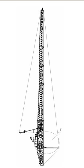
[0026] The technical scheme of the present invention is described in detail below in conjunction with accompanying drawing:

[0027] A plugging machine slotting working device, the transmission operating mechanism transmits power to the lifting mechanism through hydraulic control, the lifting mechanism drives the working device 3 to rotate, and the working device 3 is equipped with a steel casing 43 driven by hoisting. A drainage board 42 is arranged inside the steel casing 43; a left and right vertical adjustment mechanism, a retractable plate wire frame, and a detachable support device are respectively arranged on the working device 3 .

[0028] Such as figure 1 , figure 2 As shown, the left and right vertical adjustment mechanism of the present invention is to connect the first swing frame 11 on the working device 3, one end of the first swing frame 11 is connected to the oil cylinder 12 through the oil cylinder pin 14, and the other end of the oil cylinder 12 is connecte...


PUM


Abstract

A spile device of a spile machine relates to the technical field of spile machines. A transmission operating mechanism transmits power to a lifting mechanism under hydraulic control, the lifting mechanism drives the spile device to rotate, and a drain board is disposed in a steel casing which is disposed inside the spile device and driven by a winch. A left verticality adjusting mechanism, a right verticality adjusting mechanism, a pay-off and take-up type line puller and a detachable support device. The spile device has the advantages that movement is fast, action is flexible, driving depth is large, ground adaptability is high, operation is convenient, power is high and driving speed is high.

Description

[0001] technical field [0002] The invention relates to the technical field of slot machines. [0003] Background technique [0004] The slotting machine is a new type of piling machine, which is mainly used in coastal or wetland soft foundation treatment, sea reclamation and other construction fields. The operation process of the plugging machine is to insert the steel casing into the soil, bring the plastic drainage plate into the soil, pull the steel casing out of the soil and leave the plastic drainage plate in the soil, cut off the plastic drainage plate, and lift the working device From the ground, when the vehicle is walking or turning, align the steel casing with the next drainage plate hole to insert the second hole. Therefore, the machine is a self-propelled piling machine for periodic operation. [0005] At present, there are mainly three types of slotting machines on the market, one is light rail type slotting machine, the other is hydraulic walking type, and...

Claims


Application Information

Patent Timeline
IPC IPC(8): E02D3/10
CPCE02B11/02E02D3/10
Inventor 沈玉涛陈均钧印光宇刘云华吕树棠
Owner JIANGSUSNGQI GROUP
Why Eureka
Try Eureka