
Multihole floating breakwater with wave energy weakened in multiple stages

A floating breakwater and wave attenuation technology, applied in the directions of breakwaters, jetties, embankments, etc., can solve the problems of increasing the weight of the floating tank, increasing the project cost, and increasing the risk of the safety of the fixed mooring system, so as to reduce the project cost and improve the safety. The effect of sex, weight reduction and wave impact

Active Publication Date: 2012-07-18
郑先斌
View PDF8 Cites 35 Cited by
  • Summary
  • Abstract
  • Description
  • Claims
  • Application Information

AI Technical Summary

Problems solved by technology

According to the distribution characteristics of wave energy, most of the wave energy is concentrated on the surface of the water and part of the wave energy is within a certain depth below the water surface; the traditional floating breakwater uses the limited area of ​​the front wave surface of the buoyancy tank to block the impact of the wave , to achieve the effect of attenuating the wave energy of the surface of the water body, but for attenuating the wave energy of the diving wave, only by increasing the area of ​​the floating tank in the water can the effect of attenuating the deep water wave energy be achieved, thereby increasing the weight of the floating tank and increasing the fixed mooring system Safety risks, at the same time, the cost of the entire project increased sharply

Method used


Image

  • Multihole floating breakwater with wave energy weakened in multiple stages
  • Multihole floating breakwater with wave energy weakened in multiple stages
  • Multihole floating breakwater with wave energy weakened in multiple stages

Examples


Embodiment Construction

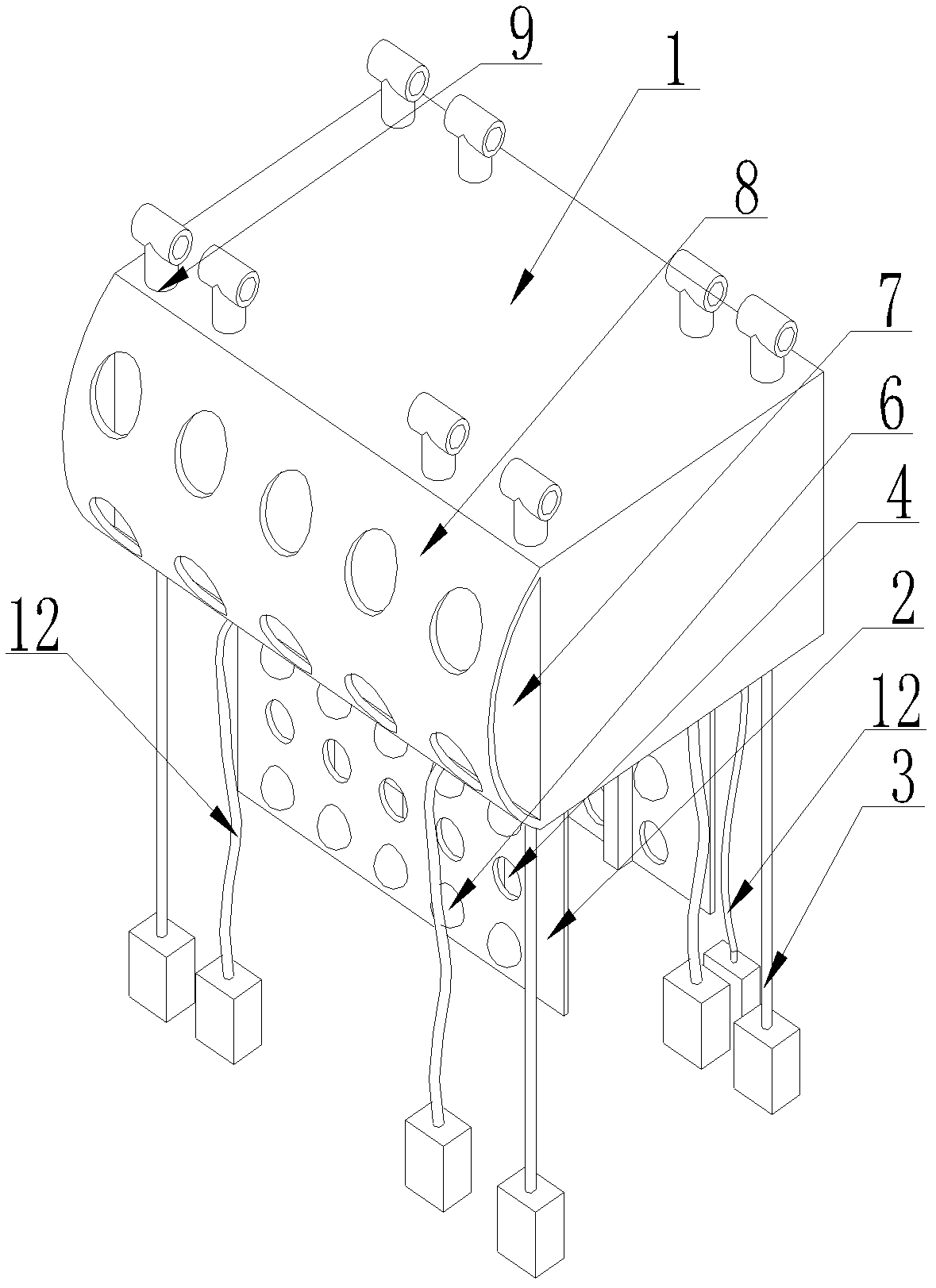
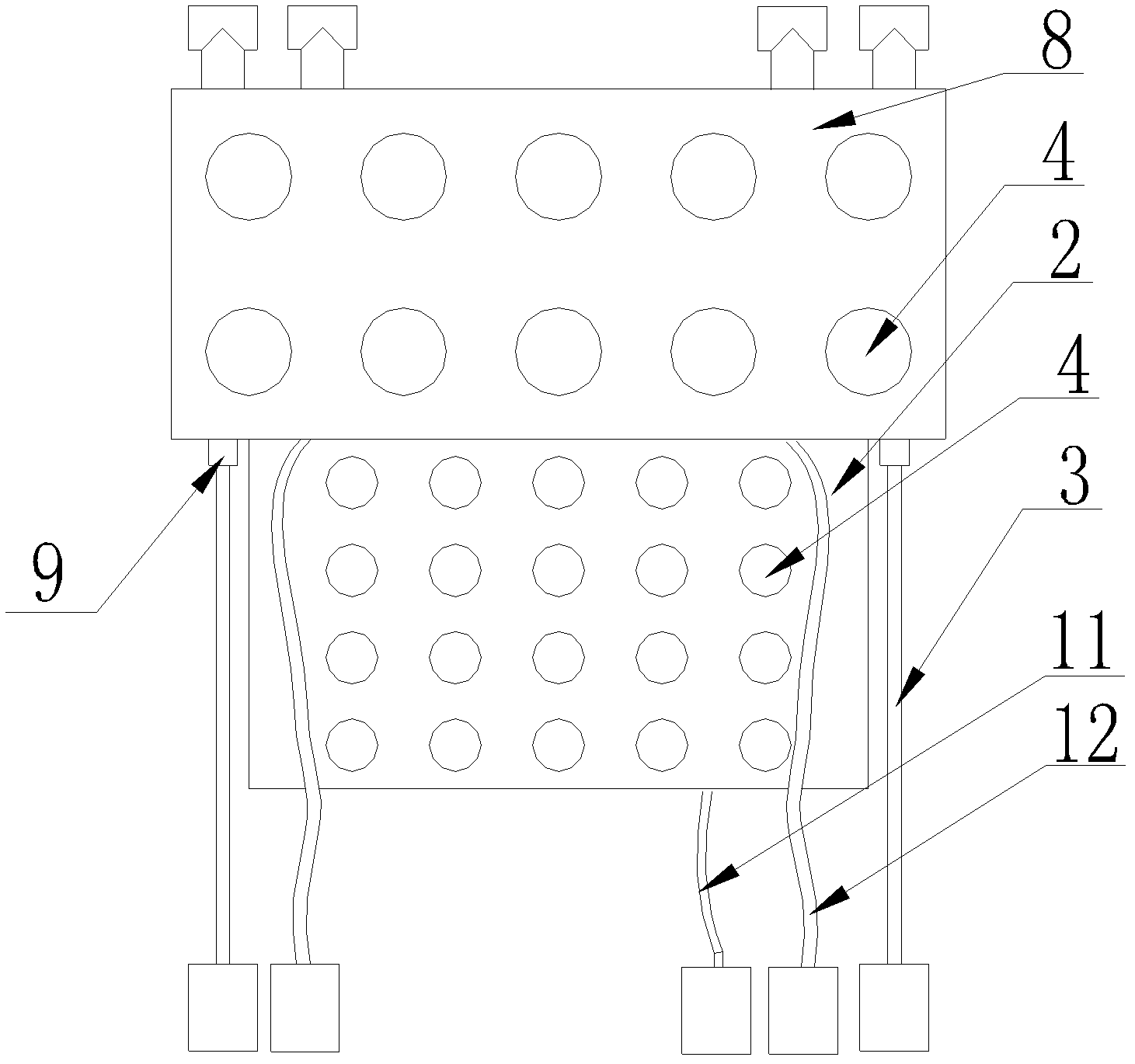
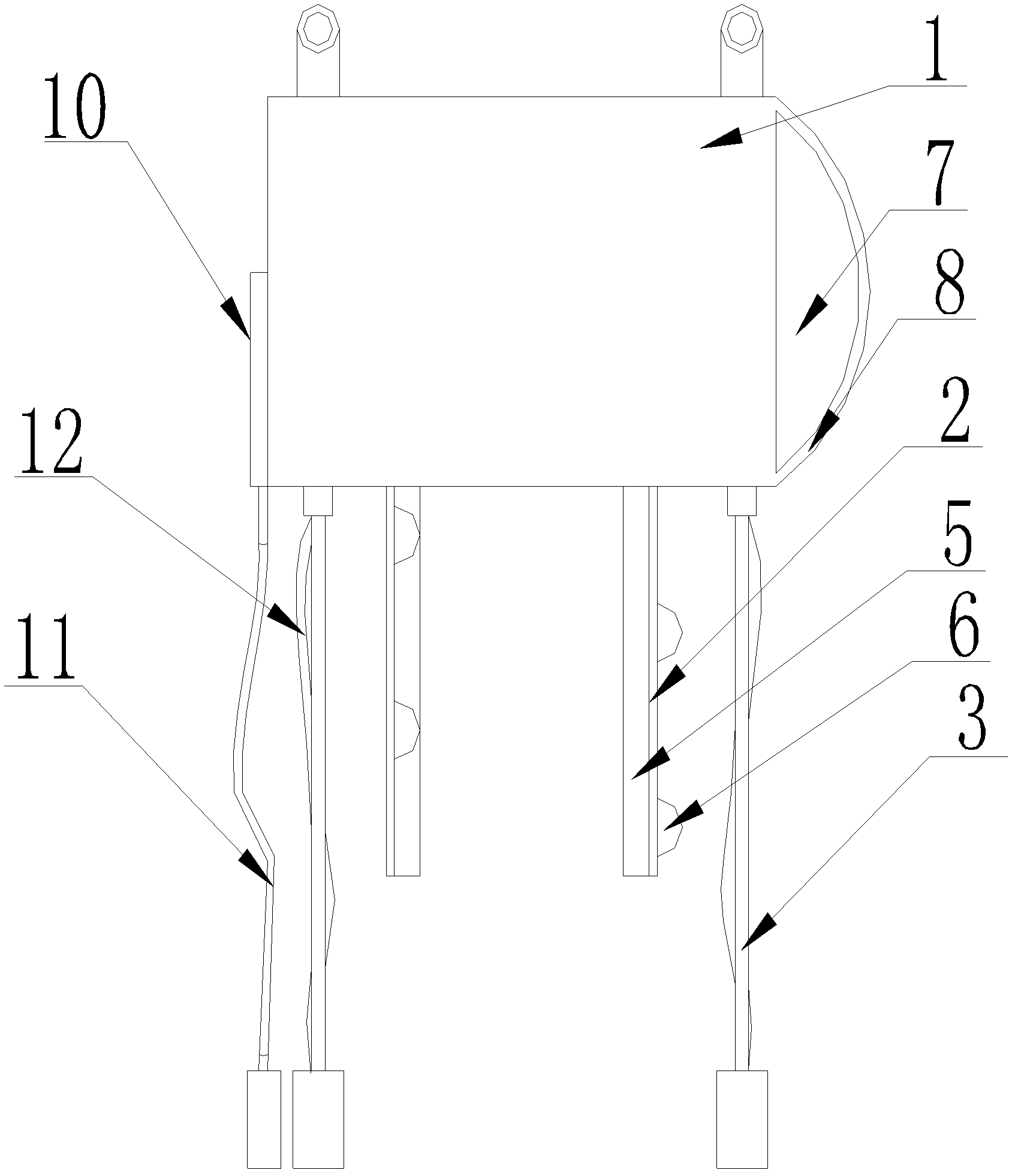
[0019] Such as figure 1 As shown, the present invention includes a buoyant tank 1, a wave breaking plate 2, and an anchoring system; the buoyant tank 1 is a fully enclosed hollow cavity, and more than one wave breaking plate 2 with a certain distance is connected to the buoyant tank The bottom of 1 is provided with wave breaking holes 4 on the wave breaking plate 2, and the wave breaking holes 4 on the adjacent wave breaking plates 2 arranged in the front and back are misplaced, and the buoyancy tank 1 is connected with the mooring system, and the mooring system is mainly It consists of an anchor sunk into the bottom of the water area and an anchor chain 3 connecting the anchor and the buoyancy box. The buoyancy tank 1 is connected with the anchor chain 3 . One end of the anchor chain is fixed or hinged on the surface of the top of the buoy.

[0020] In order to weaken the energy of the waves impacting on the front as much as possible, a horizontally arranged arc-shaped pane...


PUM


Abstract

The invention relates to a floating breaker, which comprises a floating box, wave weakening plates and an anchoring system. The more than one wave weaning plate is arranged at the bottom of the floating box in front and rear manner; a plurality of wave weakening holes are arranged on the wave weakening plates; the plurality of wave weakening holes are distributed in a staggered manner on the wave weakening plates arranged in front and rear manner; and the floating box is connected with the anchoring system. With the adoption of the floating breaker provided by the invention, the effect of weakening deep water wave energy is improved, the impact force on a wave weakening panel by waves is reduced, the weight of the integral floating breakwater and the impact force of the waves are reduced, and the security of a fixing anchoring system is promoted; when an anchor chain of the fixing anchoring system fractures or an anchor slips away, the protecting anchoring system is started immediately to play the role of protecting and fixing the anchor chain or the anchor; and if the anchor chain fractures or the anchor slips away again in the protecting anchoring system, a security anchor chain of a security anchoring system is started to automatically pull down a security door of the floating box, so that seawater flows in the floating box quickly, and the floating box sinks to the seabed. The floating breaker provided by the invention is safe and reliable and can substantially reduce the manufacturing cost of the whole engineering.

Description

technical field [0001] The invention relates to a floating breakwater. Background technique [0002] The traditional floating breakwater is a common port and coastal engineering structure. It is mainly used to defend against waves from the open sea, provide a stable operating environment for ship loading and unloading, offshore farming, yacht docks and large coastal enterprises, and protect the inside of the breakwater. Property security. According to the distribution characteristics of wave energy, most of the wave energy is concentrated on the surface of the water and part of the wave energy is within a certain depth below the water surface; the traditional floating breakwater uses the limited area of ​​the front wave surface of the buoyancy tank to block the impact of the wave , to achieve the effect of attenuating the wave energy of the surface of the water body, but for attenuating the wave energy of the diving wave, only by increasing the area of ​​the floating tank i...

Claims


Application Information

Patent Timeline
IPC IPC(8): E02B3/06
CPCY02A10/11
Inventor 郑先斌
Owner 郑先斌
Learn More