Direct twisting machine

A technology of direct twisting machine and frame, applied in spinning machine, continuous winding spinning machine, textile and papermaking, etc., can solve the problems of poor energy saving effect and large current load of machinery and equipment, and achieve obvious energy saving effect. Effect

Inactive Publication Date: 2012-07-18
JIANGSU HAIYANG CHEM FIBERS
View PDF0 Cites 2 Cited by
  • Summary
  • Abstract
  • Description
  • Claims
  • Application Information

AI Technical Summary

Problems solved by technology

Its disadvantage is that since the spindle is driven by a single spindle motor, the current load of the machine equipment is large, and the energy saving effect is poor, so it needs to be improved

Method used


Image

  • Direct twisting machine
  • Direct twisting machine
  • Direct twisting machine

Examples


Embodiment Construction

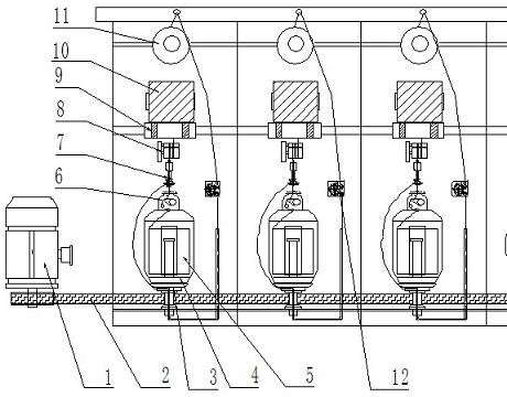
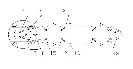
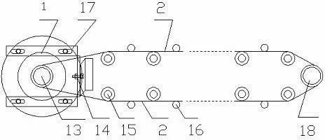
[0019] See attached figure 1 , 2 , the direct twisting machine shown in the embodiment of the present invention is symmetrically installed on the steel plate frame (not shown in the figure) by two rows of spindles 3, each row of spindles has multiple sections, each section has several spindles, and each spindle includes at least Finished package drum 10, winding roller 9, overfeed roller 8, twist leveler 7, spindle pot 4, yarn storage disc installed from top to bottom, and inner yarn package 5 and inner yarn tensioner in the spindle pot 4 6. It also includes an outer yarn creel installed on the steel plate frame, an outer yarn package 11, an outer yarn tensioner 12 and a wire guide tube, and the inner yarn is provided by the spindle yarn placed in the spindle pot 4, The outer yarn is provided by the outer yarn package 11 on the upper part of the machine through the outer yarn creel, passes through the outer yarn tensioner 12, the wire guide tube, enters from the hollow shaft...


PUM


Abstract

The invention relates to a direct twisting machine. On the basis of an existing direct twisting machine, a motor and a belt pulley are mounted at two ends of a frame respectively, a motor transmission belt pulley is mounted on an output shaft of the motor, a transmission belt is mounted between the motor transmission belt pulley and the belt pulley positioned at the other end of the frame, and wharve shafts fixedly mounted at the lower ends of spindles are driven by means of friction or meshing. The wharve shafts positioned at the lower ends of the spindles on the same row are simultaneously driven by the motor and the transmission belt, the spindles are driven to simultaneously rotate, and an energy saving effect is obvious. By the aid of a sliding tension device and a tension pulley structure, the transmission belt is ensured to keep a certain tension during operation, and a transmission effect is ensured.

Description

technical field [0001] The invention relates to a direct twisting machine used for twisting silk in the chemical fiber industry. It belongs to the production equipment for twisting process in chemical fiber production. Background technique [0002] In the prior art, there are mainly two types of twisting machines used for twisting silk in the chemical fiber industry. One is the traditional ring twisting twisting machine, which is widely used. After going down vertically, it is sent to the wire feeding device through the wire retaining rod and the porcelain ring of the yarn moving device. The wire feeding device is composed of a wire feed roller and a compression roller. The wire rod passes through the wire feed roller and then goes around the porcelain wire guide ring, and then passes through the nylon hook and is wound onto the straight-side bobbin of the disc inserted on the spindle. . In this way, the twisting of the silk thread is realized, and the double-strand threa...

Claims


Application Information

Patent Timeline
IPC IPC(8): D01H1/241
Inventor 陈建新王军周大林
Owner JIANGSU HAIYANG CHEM FIBERS
Why Eureka
Try Eureka