
Float disc feeding method for planar wafer optical parts

A technology for optical parts and sheets, applied in the field of flat sheet optical parts processing, can solve the problems of uneven pressure, damaged and scrapped parts, material and labor losses, etc., to achieve uniform pressure, reduce deformation, and reduce bonding area. Effect

Active Publication Date: 2014-08-27
CHENGDU Z & Z OPTOELECTRONICS TECH
View PDF5 Cites 0 Cited by
  • Summary
  • Abstract
  • Description
  • Claims
  • Application Information

AI Technical Summary

Problems solved by technology

At the same time, due to the rigid contact between the parts and the bonding mold, the pressure received during the processing is not uniform, and the parts are easily damaged and scrapped, resulting in material and labor losses.

Method used


Image

  • Float disc feeding method for planar wafer optical parts
  • Float disc feeding method for planar wafer optical parts

Examples


Embodiment

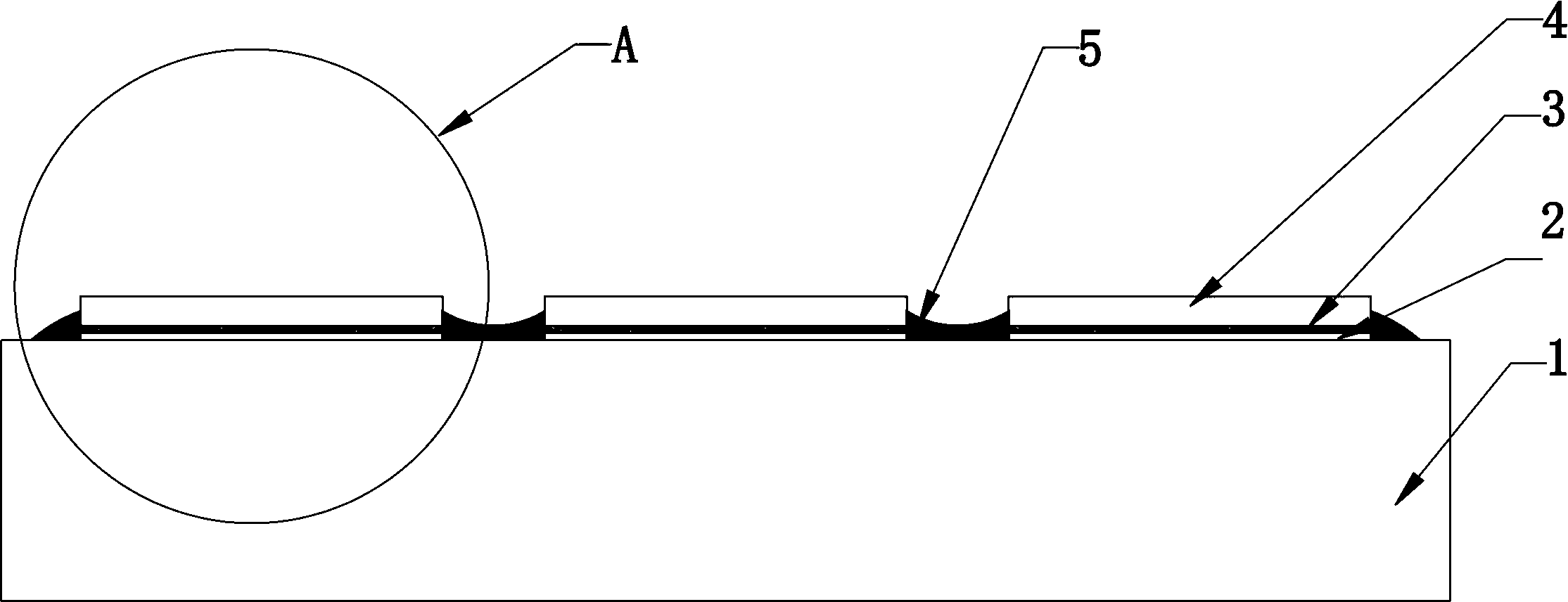
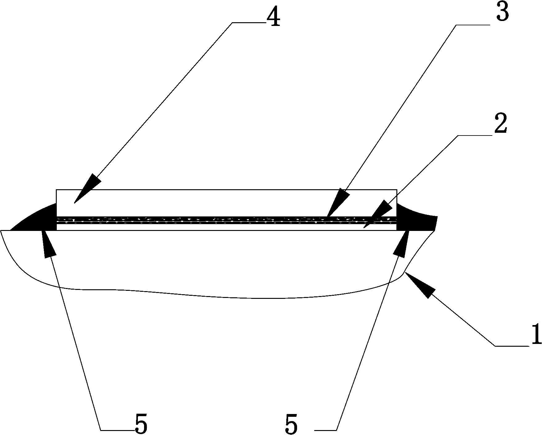
[0021] Such as figure 1 , figure 2 As shown, the float method for loading flat sheet optical parts includes the following steps:

[0022] First, cover two layers of lens paper 3 on the bonding surface of the plane thin optical part 4 to be processed, then apply foreign dry varnish, and dry for use;

[0023] Then, evenly smear one layer of castor oil 2 on the bonding mold 1, and the side of the flat sheet optical part covered with lens paper facing the bonding mold is placed on the bonding mold coated with castor oil 2. On the mold 1, and leave a gap between the flat sheet optical parts;

[0024] Finally, hot melt adhesive 5 is filled in the gaps between the planar thin optical parts. The hot melt adhesive may cool during the filling process. At this time, use a soldering iron to melt the hot melt adhesive around the part again to ensure a good bond between the hot melt adhesive and the side of the part. After cooling, the optical parts can be processed.


PUM


Abstract

The invention relates to the field of processing of planar wafer optical parts, in particular to a float disc feeding method for planar wafer optical parts. The float disc feeding method includes the steps: firstly, covering lens paper on adhesion surfaces of planar wafer optical parts to be processed, further smearing diluted shellac on the adhesion surfaces and drying the adhesion surfaces for standby application; secondly, uniformly smearing a layer of castor oil on an adhesion film, leading the surfaces, which are covered with the lens paper and dried for standby application, of the planar wafer optical parts to face the adhesion film, placing the surfaces on the adhesion film smeared with the castor oil, and reserving a gap between each two adjacent planar wafer optical parts; and finally, filling hot melt adhesive in the gaps among the planar wafer optical parts. The float disc feeding method has the advantages that deformation of surfaces of the planar wafer optical parts caused by cure shrinkage of the hot melt adhesive is prevented, consumption of the adhesive is reduced, the optical parts are firmly adhered, pressure on the parts is uniformly distributed effectively during processing, and breakage of the parts is avoided during processing.

Description

technical field [0001] The invention relates to the technical field of flat sheet optical parts processing, in particular to a float loading method for flat sheet optical parts. Background technique [0002] The entire manufacturing process of optical parts is a grinding process, which uses a special mechanical spindle to drive the corresponding grinding mold and the bonding mold that fixes the parts to be processed, and adds special abrasives to rotate the parts to be processed and drive the iron arm between the mold and the processed parts. The surface of the part is oscillated to complete the grinding and manufacturing of the entire flat sheet. [0003] If small and medium-sized planar thin optical parts are processed in a single piece, often because the size is too small, it is difficult to control the surface accuracy of the processed surface, and the processing efficiency is also very low. Therefore, for this kind of parts, the form of single-piece processing is often...

Claims


Application Information

Patent Timeline
Patent Type & Authority Patents(China)
IPC IPC(8): B24B37/07
Inventor 陈兴建曾贤高
Owner CHENGDU Z & Z OPTOELECTRONICS TECH
Learn More