
Method and device for main and standby protection of packet transport networking equipment

A packet transport network and equipment technology, applied in the field of communications, can solve the problems of slow convergence of MAC address and routing address learning, affecting switching performance, etc., to achieve the effects of fast learning convergence and improving switching performance

Inactive Publication Date: 2012-07-11
ZTE CORP
View PDF3 Cites 0 Cited by
  • Summary
  • Abstract
  • Description
  • Claims
  • Application Information

AI Technical Summary

Problems solved by technology

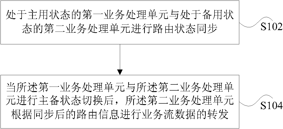
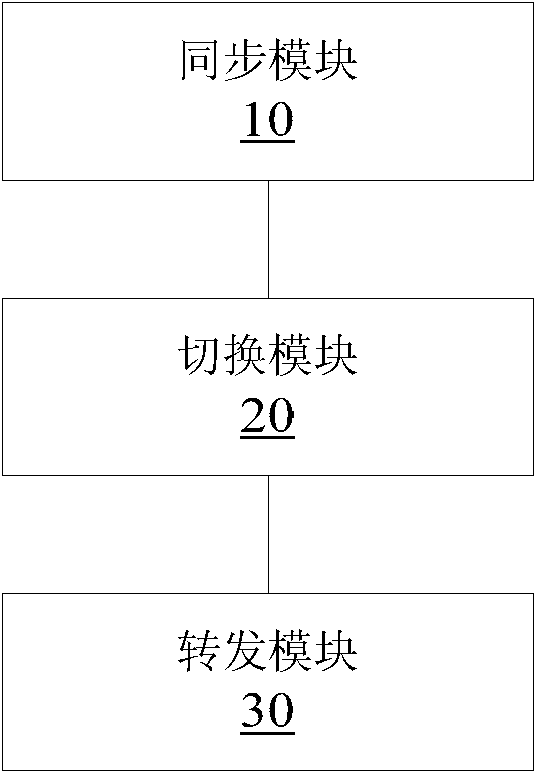
[0004] The main purpose of the present invention is to provide a method and device for active / standby protection of packet transmission network equipment, so as to at least solve the problem of slow convergence in the learning of the MAC address and routing address of the standby service processing unit and affect the switching performance

Method used


Image

  • Method and device for main and standby protection of packet transport networking equipment
  • Method and device for main and standby protection of packet transport networking equipment
  • Method and device for main and standby protection of packet transport networking equipment

Examples


Embodiment 1

[0049] In this embodiment, the service processing flow of the main / standby processing unit located upstream of the switching unit is described in detail, such as Figure 4 shown, including the following steps:

[0050] Step S402, after the interface board of the service flow in this direction receives the service, the software control module of the interface board makes a decision, and sends the service to the active / standby service processing board at the same time.

[0051] In step S404, the service processing board performs a corresponding forwarding action according to its master / standby state. If it is the active service processing board, the service will be passed to the switching board; if it is the standby service processing board, the service will not be forwarded any more.

[0052] In step S406, the service processing board performs corresponding state synchronization processing according to its master / standby state. If it is the main business processing board, it ...

Embodiment 2

[0057] In this embodiment, the service processing flow of the main / standby processing unit located downstream of the switching unit is described in detail, such as Figure 5 shown, including the following steps:

[0058] Step S502, when the ordinary service processing board located upstream of the switching board on the service flow receives the service message, it needs to judge whether the service needs to be sent to the active / standby service processing board through the switching board, and if necessary, perform subsequent processing;

[0059] Step S504, the upstream general service processing board sends data to the main service processing board through the switching board in the form of a unicast message through the unicast queue of the board, and does not send services to the standby service processing board;

[0060] In step S506, after receiving the service, the main service processing board transmits the service to the corresponding interface board. The standby serv...


PUM


Abstract

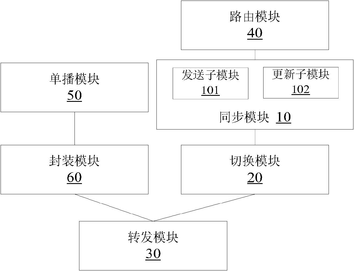
The invention provides a method and a device for main and standby protection of packet transport networking equipment. The method comprises the following steps: router state synchronization is carried out to a first service processing unit in a main state and a second service processing unit in a standby state; and after the first service processing unit and the second service processing unit are subjected to main and standby switching, the second service processing unit carries out service flow data forwarding to the synchronized router information. According to the invention, a timing processing mechanism is adopted to execute router state synchronization, so that after the main and standby switching, the convergence of an MAC (Media Access Control) address and a router address of the standby service processing unit is quicker, thereby improving the main and standby switching performance of the service processing unit.

Description

technical field [0001] The present invention relates to the field of communications, in particular to a method and device for active / standby protection of packet transmission network equipment. Background technique [0002] PTN (Packed Transport Network, Packet Transport Network) supports a variety of bidirectional point-to-point connection channels based on packet switching services, and has end-to-end networking capabilities suitable for various fine-grained services. A PTN device is usually composed of an interface unit, a service processing unit and a switching unit, wherein the interface unit completes the access of different data services. There are two types of business processing units, common business processing units and special business processing units. Both business processing units need to complete the encapsulation and sorting of data packets, and the final data will be handed over to the switching unit to complete routing / path selection and forwarding. Due ...

Claims


Application Information

Patent Timeline
IPC IPC(8): H04L12/24H04L12/56H04L45/24
Inventor 干建吴青
Owner ZTE CORP
Learn More