
Single-phase inverter

A single-phase inverter and switch tube technology, applied in the field of power electronics, can solve the problems that transformerless inverters cannot achieve electrical isolation between DC input sources and AC loads, and cannot take into account leakage current and high efficiency at the same time.

Active Publication Date: 2012-07-11
SUNGROW POWER SUPPLY CO LTD
View PDF4 Cites 5 Cited by
  • Summary
  • Abstract
  • Description
  • Claims
  • Application Information

AI Technical Summary

Problems solved by technology

[0003] Since the transformerless inverter cannot achieve electrical isolation between the DC input source and the AC load, the leakage current problem is one of the key indicators affecting its reliability
However, the traditional H4 topology can no longer take into account both leakage current and high efficiency.

Method used


Image

  • Single-phase inverter
  • Single-phase inverter
  • Single-phase inverter

Examples


Embodiment Construction

[0181] In order to make the above objects, features and advantages of the present invention more comprehensible, specific implementations of the present invention will be described in detail below in conjunction with the accompanying drawings.

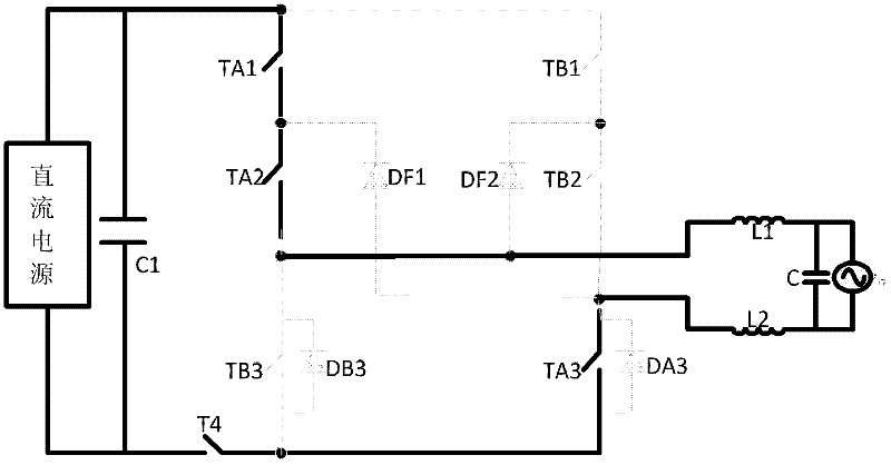
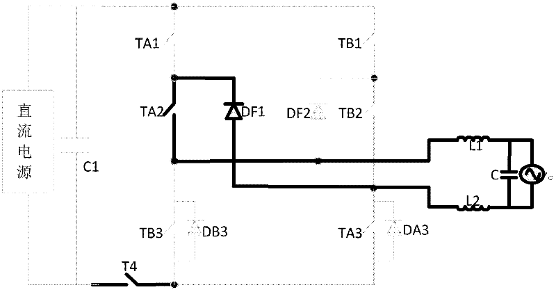
[0182] The technical problem to be solved by the present invention is to provide a single-phase inverter, improve the output power quality of the inverter, reduce the ripple of the inductor current, and solve the problem of leakage current; and further provide a single-phase inverter Modulation strategies for unity power factor and / or modulation strategies for reactive power applications.

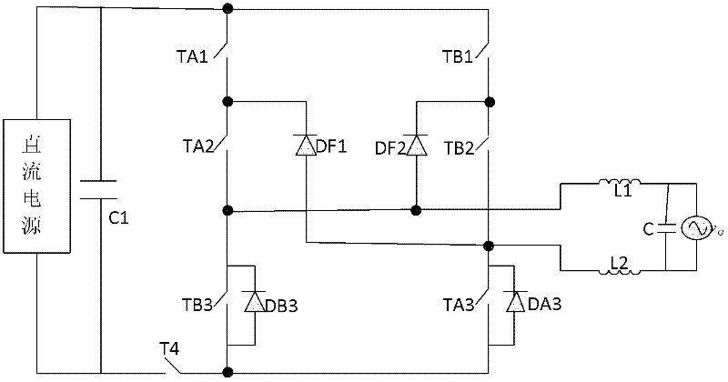
[0183] refer to figure 1 , is the topology diagram of the single-phase inverter according to the first embodiment of the present invention.

[0184] The single-phase inverter according to the first embodiment of the present invention includes: a first switching tube TA1, a second switching tube TA2, a third switching tube TA3, a fourth switching tu...


PUM


Abstract

The invention discloses a single-phase inverter, which comprises seven switching tubes. The positive end of a direct current power supply is connected with the negative end of the direct current power supply through a first switching tube, a second switching tube, a seventh switching tube and a fourth switching tube, which are sequentially connected in series. The positive end of the direct current power supply is connected with the negative end of the direct current power supply through a fifth switching tube, a sixth switching tube, a third switching tube and the fourth switching tube, which are sequentially connected in series. A first clamping diode is connected between the second end of the sixth switching tube and the second end of the first switching tube. A second clamping diode is connected between the second end of the second switching tube and the second end of the fifth switching tube. The second end of the second switching tube and the second end of the sixth switching tube are the alternating current ends of the single-phase inverter. The third switching tube is reversely connected in parallel with a third diode. The seventh switching tube is reversely connected in parallel with a seventh diode. According to the single-phase inverter in the embodiment of the invention, the quality of electric energy output by the inverter can be improved.

Description

technical field [0001] The invention relates to the technical field of power electronics, in particular to a single-phase inverter. Background technique [0002] According to different application occasions and control methods of inverters, they can be divided into off-grid inverters and grid-connected inverters. In the grid-connected inverter, according to whether it has a transformer, it can be divided into a transformer-isolated inverter and a transformerless inverter. Due to its simple system structure, high efficiency, small size, low cost and many other advantages, the transformerless inverter has been developed rapidly and has become the mainstream of photovoltaic medium and small power. [0003] Since the transformerless inverter cannot achieve electrical isolation between the DC input source and the AC load, the leakage current problem is one of the key indicators affecting its reliability. However, the traditional H4 topology can no longer take into account both ...

Claims


Application Information

Patent Timeline
IPC IPC(8): H02M7/48H02M1/42H02J3/18
CPCY02B70/126Y02E40/30Y02B70/10
Inventor 汪洪亮赵为
Owner SUNGROW POWER SUPPLY CO LTD
Learn More