
Resonant converter

A resonant converter, power conversion technology, applied in the direction of high-efficiency power electronic conversion, instruments, output power conversion devices, etc., can solve problems such as difficulty in meeting

Inactive Publication Date: 2012-07-11
SAMSUNG ELECTRO MECHANICS CO LTD
View PDF8 Cites 2 Cited by
  • Summary
  • Abstract
  • Description
  • Claims
  • Application Information

AI Technical Summary

Problems solved by technology

[0007] However, when a short circuit occurs at the output stage, the protection circuit of the resonant converter interrupts the power applied to the resonant converter to stop the drive of the resonant circuit, making it difficult to meet various needs of users who want to drive electronic devices even in the event of a short circuit

Method used


Image

  • Resonant converter
  • Resonant converter
  • Resonant converter

Examples


Embodiment approach

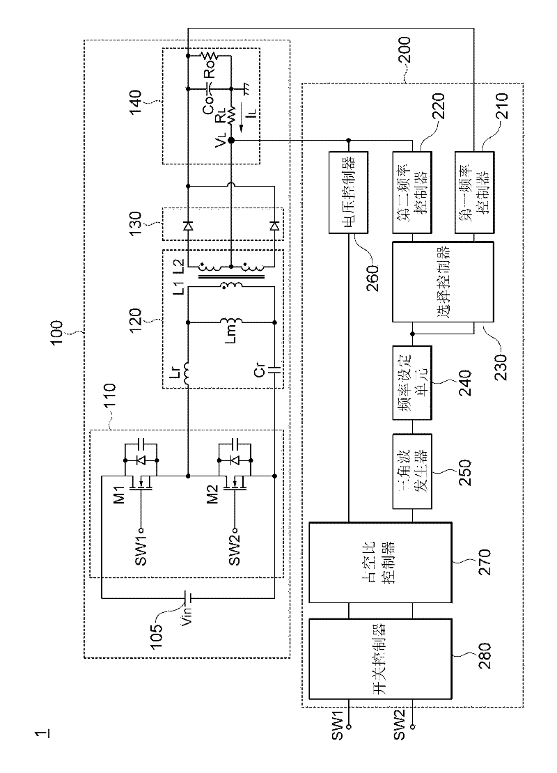
[0031] figure 1 is a configuration diagram of a resonant converter according to an exemplary embodiment of the present invention.

[0032] like figure 1 As shown in , the resonant converter 1 is configured to include a power conversion circuit 100 and a control circuit 200 .

[0033] First, an exemplary embodiment of the present invention will be described by taking an inductance-inductance-capacitance (LLC) resonant converter as an example among the resonant converters.

[0034] The power conversion circuit 100 is a device that alternately switches (alternately turns on / off) applied DC power Vin to achieve a predetermined level of output power Vo. The power conversion circuit 100 is configured to include a switching unit 110 , a converter 120 , a rectifier 130 and a smoothing output unit 140 .

[0035] The switch unit 110 includes a first switch M1 and a second switch M2, the first switch and the second switch are connected in series between two electrodes (positive (+) el...


PUM


Abstract

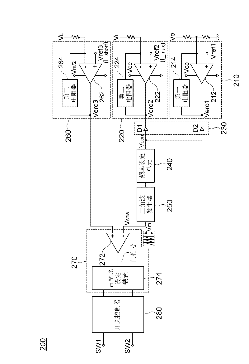
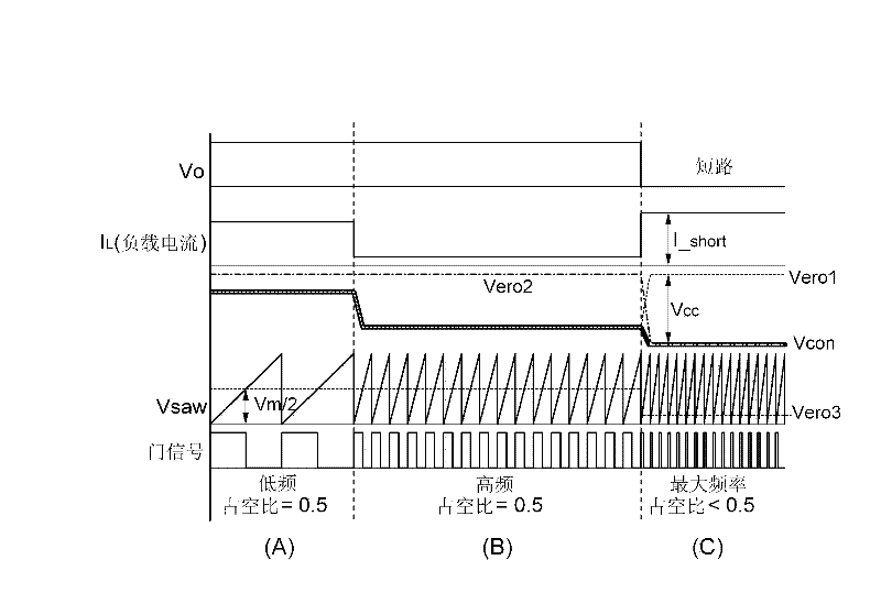
Disclosed herein is a resonant converter, including: a power conversion circuit alternately switching applied DC power to output a predetermined level of output power; and a control circuit fixing an operating frequency and controlling the level of the output power by varying the comparison voltage level that is a comparison target of the operating frequency, by determining that a short circuit occurs when the output current of the power conversion circuit is a reference current or more by comparing the output current of the power conversion circuit with the reference current. By this configuration, the output current can be constantly controlled even when the short circuit occurs in the output end of the resonant converter.

Description

[0001] Cross References to Related Applications [0002] This application claims the benefit of Korean Patent Application No. 10-2010-0134696 filed on December 24, 2010, entitled "Resonant Converter", the entire contents of which are incorporated herein by reference. technical field [0003] The present invention relates to a resonant converter, and more particularly, to a resonant converter for a power supply such as a switched mode power supply (SMPS). Background technique [0004] Generally, in order to drive electronic equipment such as an air conditioner, audio equipment, personal computer, etc., a power supply such as a switch mode power supply (SMPS) or the like is required. [0005] A switching power supply refers to a device that converts a DC voltage into a sine wave voltage using a switching device such as a Metal Oxide Semiconductor Field Effect Transistor (MOSFET), and then outputs a DC voltage of a desired level using a resonant converter. [0006] At the same...

Claims


Application Information

Patent Timeline
Patent Type & Authority Applications(China)
IPC IPC(8): H02M3/335
CPCH02M2001/325Y02B70/1433H02M3/3387H02M1/325Y02B70/10
Inventor 洪成洙卢正煜韩翔圭金钟海元载善李泰远金镇郁
Owner SAMSUNG ELECTRO MECHANICS CO LTD
Learn More