
Current-limiting and voltage-limiting lithium battery charge circuit based on comparer

A technology of current limiting and voltage limiting, charging circuit, applied in battery circuit devices, circuit devices, current collectors, etc., can solve the problems of low charging efficiency, low cost, and high cost, and achieve simple and scientific structural design, high reliability, and cost. low effect

Inactive Publication Date: 2012-07-11
东莞市妙达电动工具制造有限公司
View PDF5 Cites 2 Cited by
  • Summary
  • Abstract
  • Description
  • Claims
  • Application Information

AI Technical Summary

Problems solved by technology

[0002] At present, in the field of lithium battery charging technology for some electrical appliances, lithium battery chargers using low-voltage DC power supply generally use professional charging ICs or use single-chip microcomputers to charge them with constant current and constant voltage. This solution has better results, but the cost is higher.
[0003] There are also other linear circuits to directly charge lithium batteries. This solution is low in cost, but it generates a lot of heat, has low charging efficiency, and is easy to damage the battery.

Method used


Image

  • Current-limiting and voltage-limiting lithium battery charge circuit based on comparer
  • Current-limiting and voltage-limiting lithium battery charge circuit based on comparer
  • Current-limiting and voltage-limiting lithium battery charge circuit based on comparer

Examples


Embodiment Construction

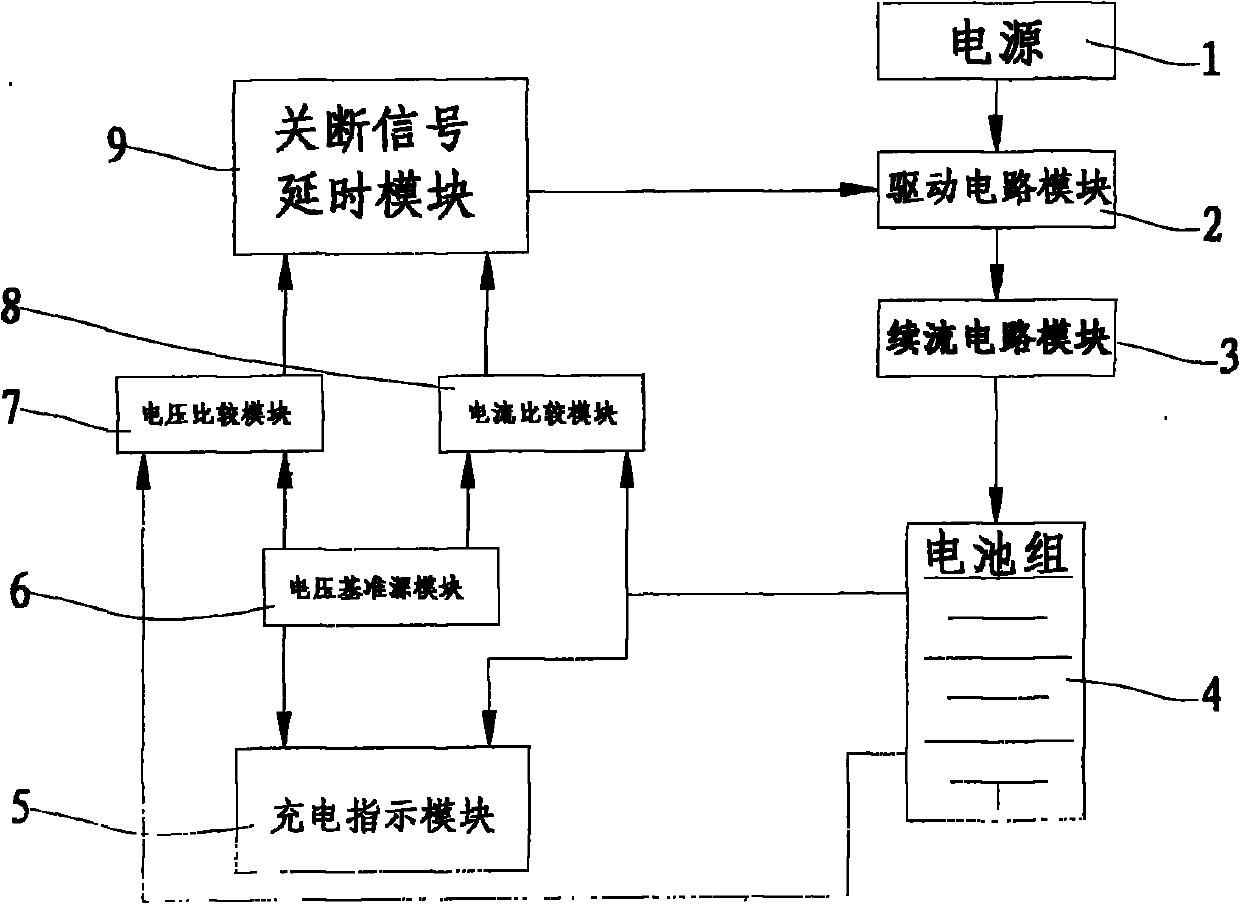
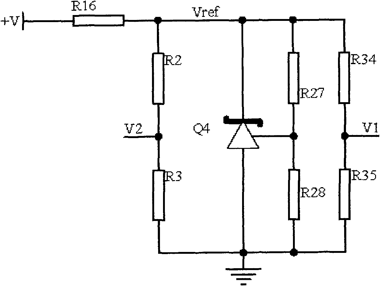
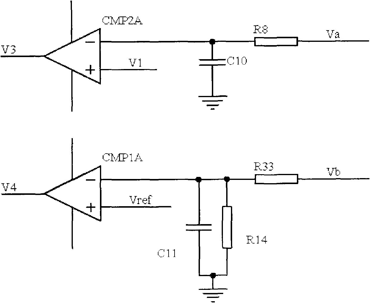
[0016] See Figure 1 to Figure 6 As shown: the present invention includes a power supply 1, a driving circuit module 2, a freewheeling circuit module 3, a battery pack 4, a charging indication module 5, a voltage reference source module 6, a voltage comparison module 7, a current comparison module 8, and a shutdown signal delay Module 9, power supply 1, drive circuit module 2, freewheeling circuit module 3, and battery pack 4 are connected in series, battery pack 4 is electrically connected to charging indication module 5, voltage comparison module 7, and current comparison module 8, and voltage reference source module 6 They are respectively electrically connected to the charging indication module 5, the voltage comparison module 7, and the current comparison module 8. The voltage comparison module 7 and the current comparison module 8 are respectively electrically connected to the input terminals of the shutdown signal delay module 9, and the shutdown signal delay module 9 T...


PUM


Abstract

The invention relates to the technical field of power supply circuits, in particular relates to a current-limiting and voltage-limiting lithium battery charge circuit based on a comparer. A power supply, a driving circuit module, a follow current circuit module and a battery pack are connected in series; the battery pack is electrically connected with a charging indicating module, a voltage comparing module and a current comparing module respectively; a voltage reference source module is electrically connected with the charging indicating module, the voltage comparing module and the current comparing module respectively; and the voltage comparing module and the current comparing module are electrically connected with the input end of a turning-off signal delay module respectively, and the input end of the turning-off signal delay module is electrically connected with the driving circuit module. The current-limiting and voltage-limiting lithium battery charge circuit has a simple and scientific structure design, completes functions of current limiting, voltage limiting, charge indicating and the like of switching mode control, and has the advantages of low cost, high efficiency and high reliability.

Description

Technical field: [0001] The invention relates to the technical field of power supply circuits, in particular to a current-limiting and voltage-limiting lithium battery charging circuit based on a comparator. Background technique: [0002] At present, in the field of lithium battery charging technology for some electrical appliances, lithium battery chargers using low-voltage DC power supply generally use professional charging ICs or use single-chip microcomputers to charge them with constant current and constant voltage. This solution has better results, but the cost is higher. [0003] There are also other linear circuits to directly charge the lithium battery. This solution is low in cost, but it generates a lot of heat, has low charging efficiency, and is easy to damage the battery. Invention content: [0004] The purpose of the present invention is to address the deficiencies in the prior art and provide a current-limiting and voltage-limiting lithium battery charging ...

Claims


Application Information

Patent Timeline
IPC IPC(8): H02J7/00
Inventor 张耀霞
Owner 东莞市妙达电动工具制造有限公司
Learn More