
Product quality aging testing system

A technology for aging testing and product quality, which is applied in measuring electricity, measuring devices, and measuring electrical variables, etc. It can solve problems such as low feedback energy, frequency converter explosion, and high current harmonic content, so as to reduce transformer load and load cost. , Improve the effect of power quality

Inactive Publication Date: 2012-07-11
DELTA ELECTRONICS SHANGHAI CO LTD +2
View PDF3 Cites 5 Cited by
  • Summary
  • Abstract
  • Description
  • Claims
  • Application Information

AI Technical Summary

Problems solved by technology

The existing BI system uses magnetic confinement control (Pole-Restraining Control, PRC) as the power recovery unit, but the average power recovery efficiency is not high (about 50%), and the effect is limited
In addition, the stability of the system is poor and the production capacity is low, so it does not meet the current production requirements and the concept of "environmental protection and energy saving"
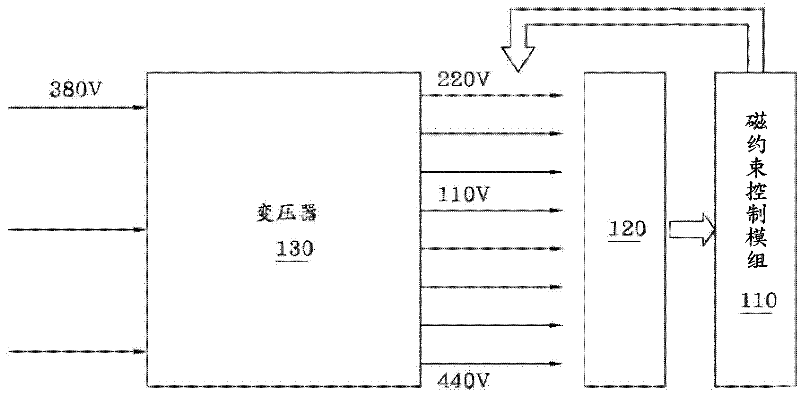
[0004] figure 1 It shows a known product quality aging test system 100, which has a transformer 130, and a magnetic confinement control module 110 as a power recovery unit, and finally the power is returned to the input terminal of the electronic product 120 through 220V, and the average power recovery efficiency is 50%. limited
In addition, the magnetic confinement control module 110 of the product quality aging test system 100 also has many shortcomings, such as poor control, which leads to serious current distortion (such as Image 6 As shown in the curve marked 610 in the middle), it seriously affects the quality of the power grid; the reliability is poor, and abnormalities often occur, which makes the inverter often crash during the loading process; the current harmonic content is high (above 30%), resulting in less feedback energy, low efficiency
[0005] It can be seen that the above-mentioned existing BI system obviously still has inconvenience and defects, and needs to be further improved.
In order to solve the above problems, related fields have tried their best to find a solution, but no applicable method has been developed for a long time.

Method used


Image

  • Product quality aging testing system
  • Product quality aging testing system
  • Product quality aging testing system

Examples


Embodiment Construction

[0035] In order to make the description of the present invention more detailed and complete, reference may be made to the accompanying drawings and various embodiments described below, and the same numbers in the drawings represent the same or similar elements. On the other hand, well-known elements and steps have not been described in the embodiments in order to avoid unnecessarily limiting the invention.

[0036] In the detailed description and the claims, the description of "coupled with" can generally refer to an element being indirectly connected to another element through other elements, or an element is connected without other elements. Connect directly to another component.

[0037] In the detailed description and claims, "a" and "the" can generally refer to a single or plural, unless there is a special limitation on the articles in the context.

[0038] As used herein, "about," "approximately," or "approximately" is used to modify any quantity that may vary slightly,...


PUM


Abstract

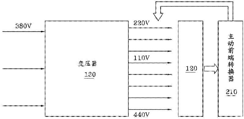
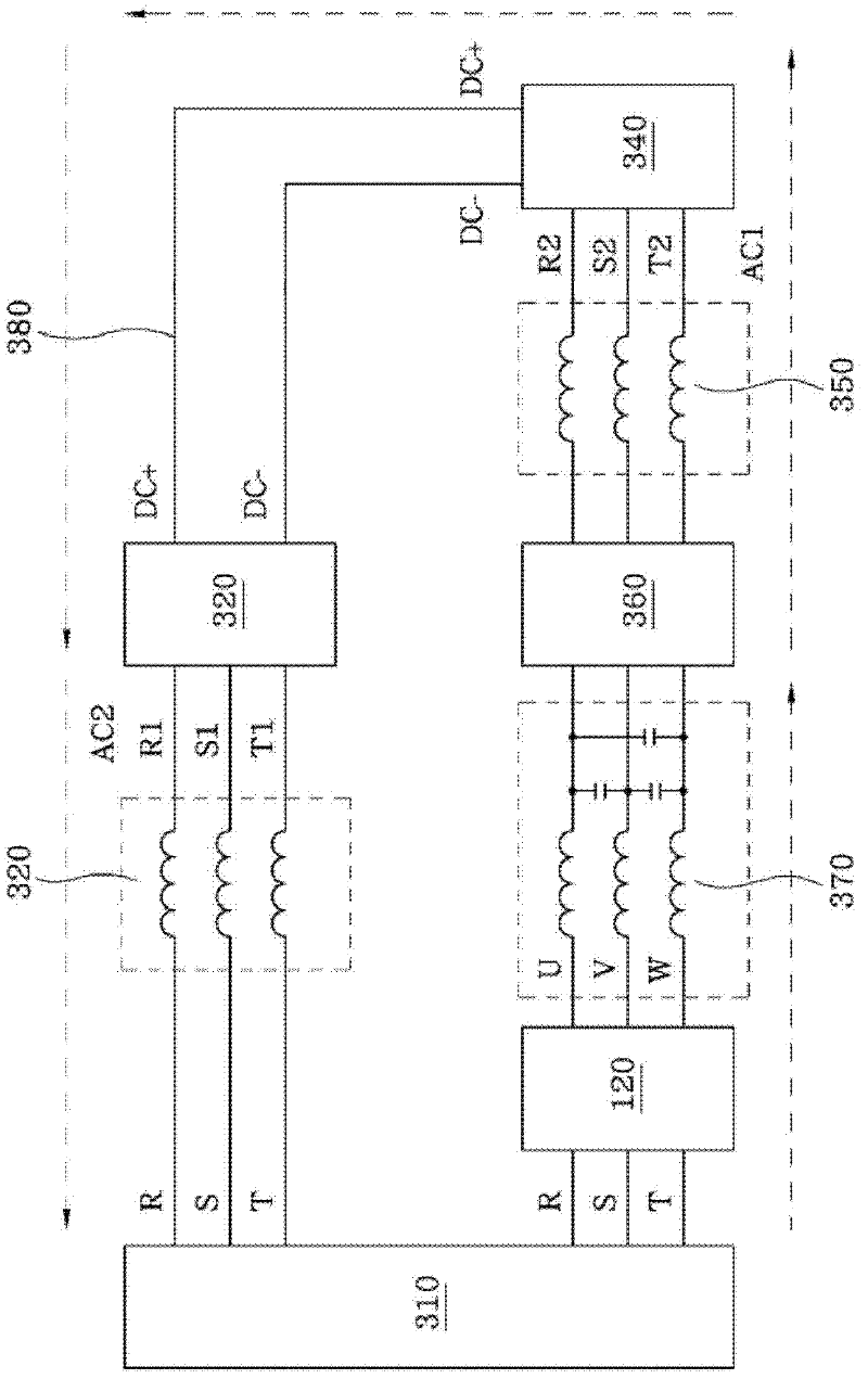
The invention provides a product quality aging testing system, which comprises a transformer and an active front end convertor. The transformer is used for supplying power to at least one kind of electronic product, and the active front end convertor is electrically coupled with the transformer and the electronic product to recover electric energy outputted from the electronic product into the input terminal of the electronic product. As the average recovery efficiency of the active front end convertor is about 80 percent, the product quality aging testing system can achieve considerable technical advancement, has a wide utilization value in the industry, and at least has the advantages of saving energy, enhancing capacity, improving utility power quality, reducing transformer load, improving equipment stability, reducing load cost and the like.

Description

technical field [0001] The invention relates to a test system, in particular to a product quality aging test system. Background technique [0002] In recent years, due to the development of industry and commerce and social progress, the relatively developed products are also aimed at environmental protection. Therefore, the currently developed products are also more energy-saving and low-carbon than before, and can contribute to society. [0003] BI (Burn-in) system, that is, the product quality aging test system, achieves the purpose of quality inspection by continuously loading the product with current. The existing BI system uses magnetic confinement control (Pole-Restraining Control, PRC) as the electric energy recovery unit, but the average electric energy recovery efficiency is not high (about 50%), and the effect is limited. In addition, the stability of the system is poor and the production capacity is low, so it does not meet the current production requirements and...

Claims


Application Information

Patent Timeline
Patent Type & Authority Applications(China)
IPC IPC(8): H02J3/38G01R31/00
Inventor 李小艳颜良益刘妙顾青苏
Owner DELTA ELECTRONICS SHANGHAI CO LTD
Learn More