
Thin-film amorphous silicon N-type crystalline silicon heterojunction tandem solar cell

A technology of amorphous silicon intrinsic layer and crystalline silicon, which is applied in the direction of circuits, photovoltaic power generation, electrical components, etc., can solve the problems of small diffusion length of electrons and holes, increased cost, and increased thickness, so as to reduce the S-W effect, The effect of reducing the thickness of the material and increasing the open circuit voltage

Inactive Publication Date: 2012-07-11
TRINA SOLAR CO LTD
View PDF3 Cites 16 Cited by
  • Summary
  • Abstract
  • Description
  • Claims
  • Application Information

AI Technical Summary

Problems solved by technology

[0002] The existing amorphous silicon thin-film battery has the characteristics of high open circuit voltage, but the amorphous silicon material itself has the characteristics of amorphous, and the diffusion length of electrons and holes is small, which can only be obtained by the migration current formed by the built-in electric field. , the short-circuit current is small, and the overall efficiency of silicon-based thin-film cells is not high; due to the need to absorb the energy of sunlight, the thickness of the intrinsic layer of amorphous silicon is relatively thick, generally several hundred nanometers, and its inherent light-induced degradation effect (S-W effect), The photoelectric conversion efficiency will be further reduced
[0003] Crystalline silicon cells have good lattice integrity, and photogenerated electron-hole pairs are realized by diffusion current. However, due to its small forbidden band width and low open circuit voltage, and the small absorption coefficient of crystalline silicon, silicon wafers must A thicker thickness can fully absorb photons, but as the thickness increases, the cost also increases

Method used


Image

  • Thin-film amorphous silicon N-type crystalline silicon heterojunction tandem solar cell
  • Thin-film amorphous silicon N-type crystalline silicon heterojunction tandem solar cell

Examples


Embodiment Construction

[0012] The present invention will be further described now in conjunction with accompanying drawing. These drawings are simplified schematic diagrams only to illustrate the basic structure of the present invention in a schematic way, so they only show the components relevant to the present invention.

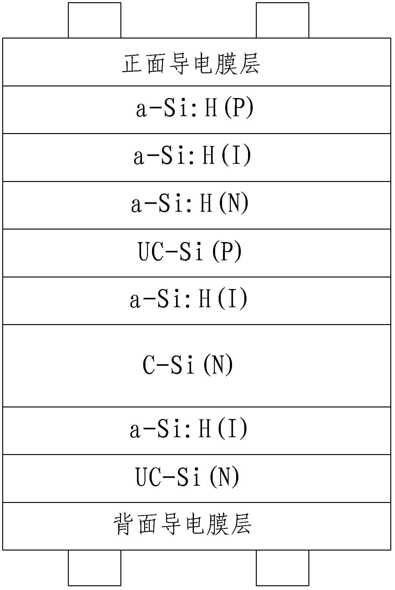
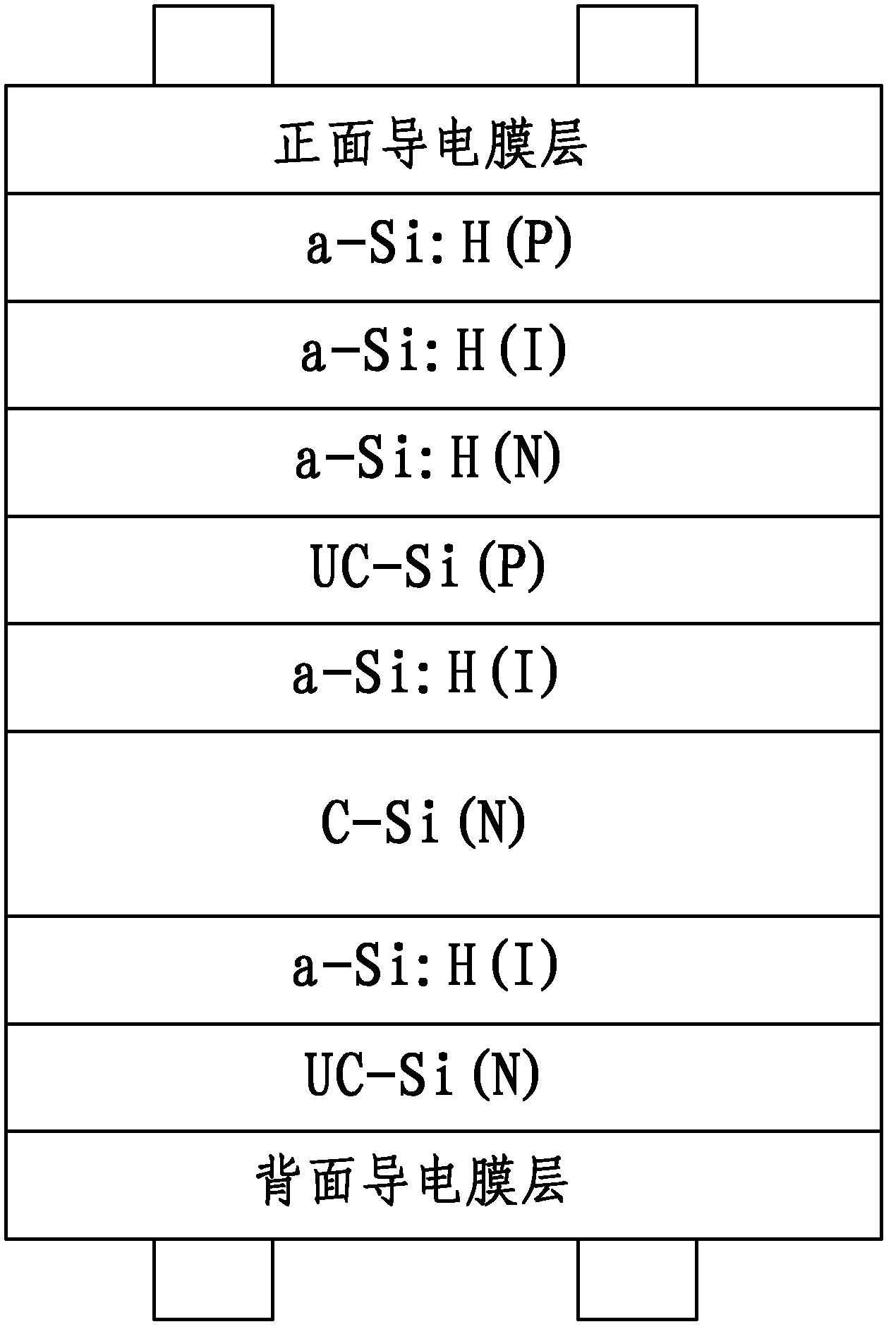
[0013] Such as figure 1 As shown, a thin-film amorphous silicon-N-type crystalline silicon heterojunction tandem solar cell has an N-type crystalline silicon substrate, and a rear amorphous silicon intrinsic layer with a thickness of 2 to 10 nm is deposited on the back of the N-type crystalline silicon substrate. After passivation of the back side amorphous silicon intrinsic layer, an N-type microcrystalline silicon layer with a thickness of 5-15 nm is deposited, and the front side of the N-type crystalline silicon substrate is deposited with a front-side first amorphous silicon intrinsic layer with a thickness of 2-10 nm. After passivation of the first intrinsic layer of amorp...


PUM

PropertyMeasurementUnit
Thicknessaaaaaaaaaa
Thicknessaaaaaaaaaa
Thicknessaaaaaaaaaa

Abstract

The invention relates to a thin-film amorphous silicon N-type crystalline silicon heterojunction tandem solar cell, which comprises an N-type crystalline silicon matrix, wherein a back-side amorphous silicon intrinsic layer with the thickness of 2 to 10nm is deposited on the back side of the N-type crystalline silicon matrix; an N-type microcrystalline silicon layer with the thickness of 5 to 15nm is deposited on the passivated back side of the back-side amorphous silicon intrinsic layer; a front-side first amorphous silicon intrinsic layer with the thickness of 2 to 10nm is deposited on the front side of the N-type crystalline silicon matrix; a P-type microcrystalline silicon layer with the thickness of 10 to 20nm is deposited on the passivated front side of the front-side first amorphous silicon intrinsic layer; and an N-type amorphous silicon layer with the thickness of 5 to 15nm, a front-side second amorphous silicon intrinsic layer with the thickness of 50 to 200nm and a P-type amorphous silicon layer with the thickness of 10 to 20nm are deposited on the front side of the P-type microcrystalline silicon layer in turn. By the solar cell, the thickness of an amorphous silicon intrinsic film can be reduced, and the utilization rate of sunlight can be improved; and therefore, the efficiency of the solar cell is improved.

Description

technical field [0001] The invention relates to a thin-film amorphous silicon-N type crystalline silicon heterojunction laminated solar cell. Background technique [0002] The existing amorphous silicon thin-film battery has the characteristics of high open circuit voltage, but the amorphous silicon material itself has the characteristics of amorphous, and the diffusion length of electrons and holes is small, which can only be obtained by the migration current formed by the built-in electric field. , the short-circuit current is small, and the overall efficiency of silicon-based thin-film cells is not high; due to the need to absorb the energy of sunlight, the thickness of the intrinsic layer of amorphous silicon is relatively thick, generally several hundred nanometers, and its inherent light-induced degradation effect (S-W effect), The photoelectric conversion efficiency will be further reduced. [0003] Crystalline silicon cells have good lattice integrity, and photogene...

Claims


Application Information

Patent Timeline
IPC IPC(8): H01L31/0747H01L31/0352H01L31/20
CPCY02E10/50Y02P70/50
Inventor 包健
Owner TRINA SOLAR CO LTD
Learn More