Automatic station reporting system of bus
A technology for automatically reporting stations and buses, applied in traffic control systems, traffic control systems for road vehicles, instruments, etc., to achieve the effects of improving anti-interference ability and reliability, reducing operations, and improving safety
Inactive Publication Date: 2012-07-11
毛振刚
View PDF7 Cites 3 Cited by
- Summary
- Abstract
- Description
- Claims
- Application Information
AI Technical Summary
Problems solved by technology
However, most of the bus lines in small and medium-sized cities have not yet fully adopted the automatic stop announcement system, and there is an urgent need for an automatic stop announcement device with low cost, reliable operation, easy maintenance, and easy promotion.
Method used
View moreImage
Smart ImageViewing Examples


Examples
Embodiment Construction
Login to View More PUM
 Abstract
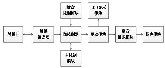
The invention relates to an automatic station reporting system of a bus. The system is mainly technically characterized by comprising a radio frequency reader, a radio frequency card, a microcontroller, a keyboard control module, a light emitting diode (LED) display module, a voice broadcasting module, a driving module, a loudspeaker module and a main control module, wherein the radio frequency reader, the microcontroller and the driving module are sequentially connected; the LED display module and the voice broadcasting module are respectively connected with the driving module; the loudspeaker module is connected with the voice broadcasting module; the keyboard control module is connected with the microcontroller; and the microcontroller is connected with the main control module through a network. According to the system, code signals emitted by the radio frequency card installed in a bus station are received and identified by the radio frequency reader, and a vehicle-mounted broadcasting system is controlled to report a station, so that real automatic station identification and automatic station reporting are realized; and because manual intervention is not required in the identification and station reporting process, operation of a driver is reduced, and the running safety of the bus is improved.
Description
technical field [0001] The invention belongs to the technical field of electronic control, in particular to an automatic bus stop reporting system. Background technique [0002] With the rapid development of my country's economy, people's opportunities to travel are gradually increasing, and the role of buses in daily life is becoming more and more prominent, thus putting forward higher requirements for the safe operation of urban public transport systems. At present, unmanned ticket sales have been realized on buses in many cities above the medium level, and bus drivers are more responsible for driving safety. This is an urgent need to install automatic stop announcers on every bus. In recent years, domestic scholars have gradually carried out research work in this area, and have designed various automatic bus stop reporting systems using technologies such as single-chip microcomputers, embedded processors, wireless sensor networks, and GPS, which have played a very good r...
Claims
Login to View More Application Information
Patent Timeline
 IPC IPC(8): G08G1/0962G08G1/133
Inventor 毛振刚
Owner 毛振刚
Features
- Generate Ideas
- Intellectual Property
- Life Sciences
- Materials
- Tech Scout
- Unparalleled Data Quality
- Higher Quality Content
- 60% Fewer Hallucinations
Learn More Browse by: Latest US Patents, China's latest patents, Technical Efficacy Thesaurus, Application Domain, Technology Topic, Popular Technical Reports.
© 2025 PatSnap. All rights reserved.Legal|Privacy policy|Modern Slavery Act Transparency Statement|Sitemap|About US| Contact US: help@patsnap.com