
Valve device for exhaust duct

An air exhaust duct and valve device technology, which is applied to valve devices, control valves, vertical pipes, etc., can solve the problem of unreasonable connection between the check valve body and the air exhaust duct, inconvenient disassembly, cleaning and maintenance of the check valve. Inability to discharge oil fume and dirt and other problems, to achieve the effect of easy disassembly, cleaning and maintenance, ensuring smooth exhaust, and preventing adhesion

Inactive Publication Date: 2012-07-11
王达
View PDF0 Cites 0 Cited by
  • Summary
  • Abstract
  • Description
  • Claims
  • Application Information

AI Technical Summary

Problems solved by technology

[0002] At present, the check valves used in the exhaust ducts of buildings and houses are generally composed of a check valve body and a check valve plate (wind deflector). On the upper part of the check valve body, the check valve plate hangs down naturally by its own gravity, and closes the exhaust duct downward. It is closed by its own gravity. Since all kinds of oil fume and dirt discharged from the exhaust duct are very viscous and flow downward, it is easy to make the lower part of the check valve plate stick to the check valve body, and the check valve cannot be opened when exhaust air is required. The check valve piece and the check valve cannot work normally, and cannot discharge oil fumes and dirt; in addition, the connection between the check valve body and the exhaust duct is unreasonable, and the disassembly, cleaning and maintenance of the check valve are very inconvenient

Method used


Image

  • Valve device for exhaust duct
  • Valve device for exhaust duct
  • Valve device for exhaust duct

Examples


Embodiment Construction

[0019] Below in conjunction with the accompanying drawings, the present invention will be further described through embodiments.

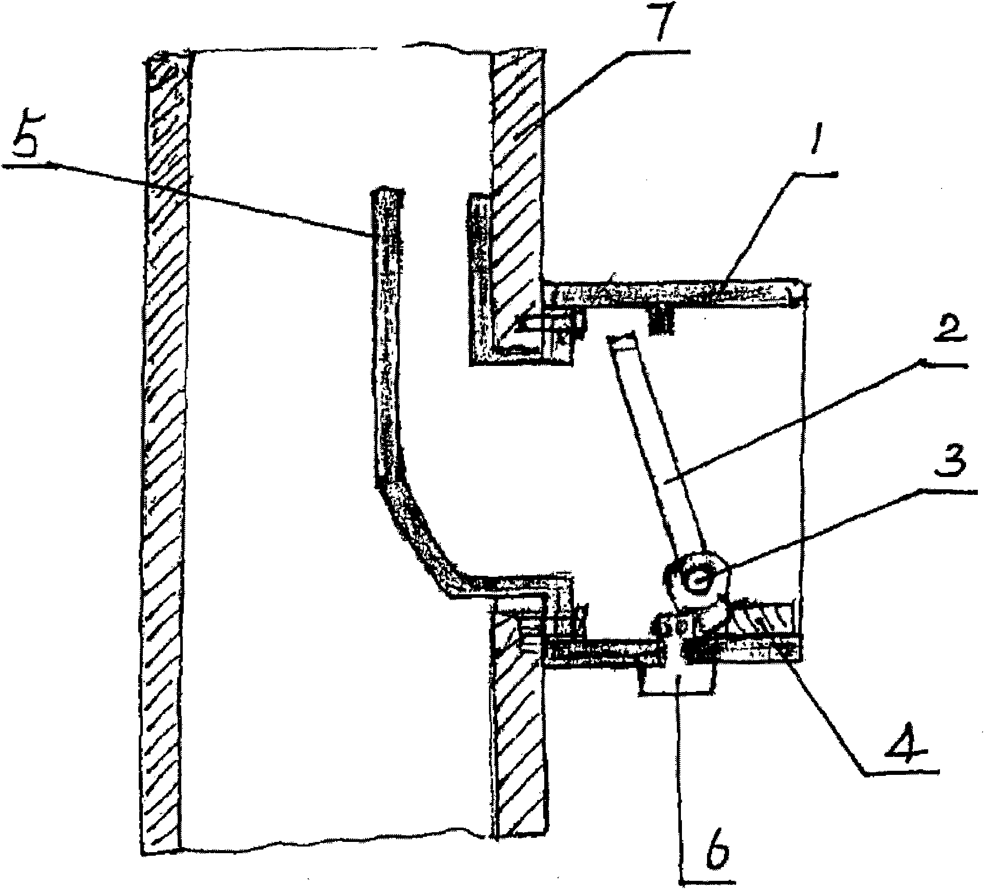
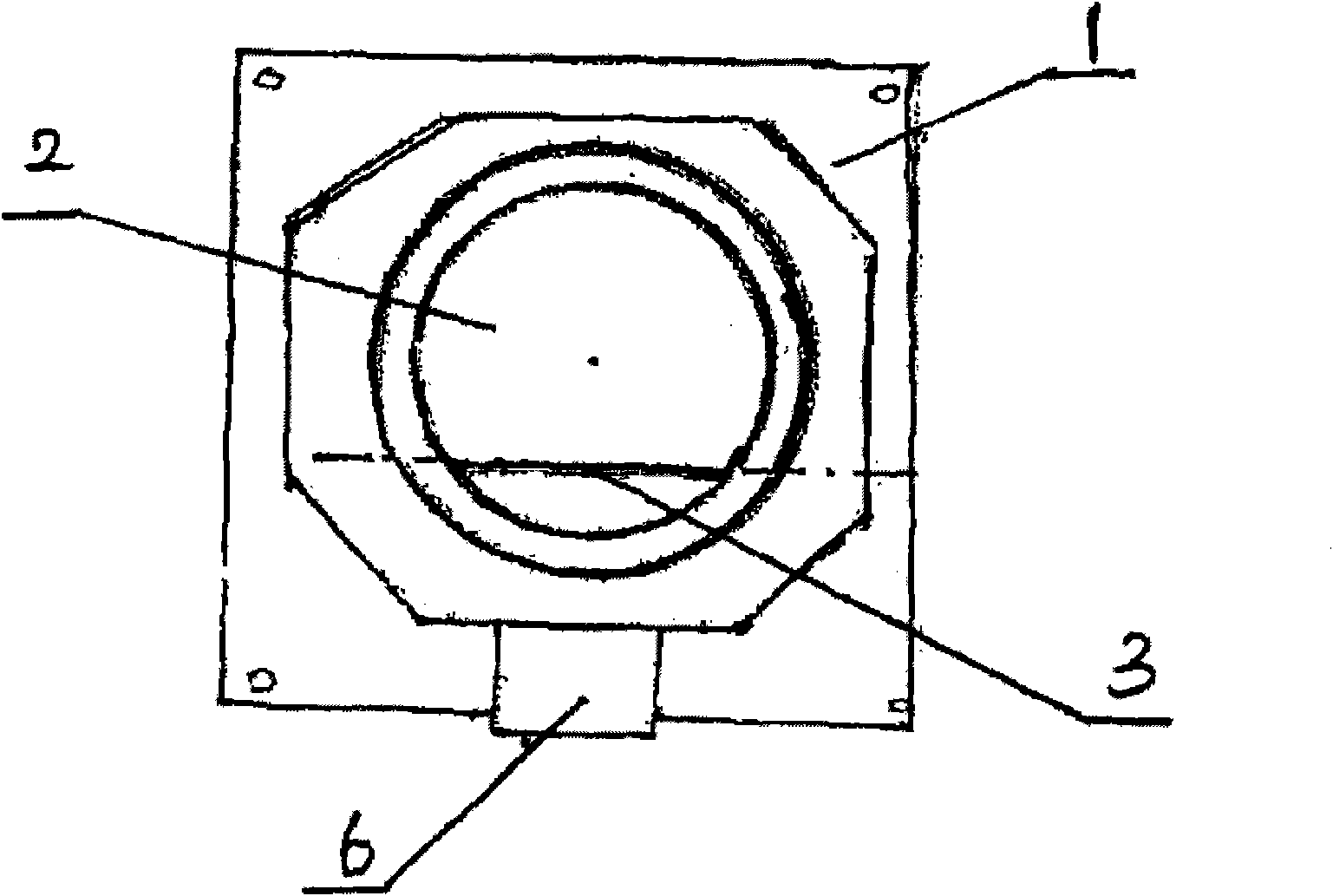
[0020] In the embodiment, the composition of the present invention includes a first check valve body 1 and a second check valve plate 2. The second check valve plate 2 is arranged on the first check valve body 1 through a hinge shaft 3, and the reverse check valve is closed upward. The passage in the check valve, the hinge shaft 3 is located at the lower part of the first check valve body 1 , and a counterweight body 4 is provided on the check valve sheet at the lower part of the hinge shaft 3 , and the weight of the counterweight body 4 is the same as that of the second check valve sheet 2 . weights match each other. The first check valve body 1 and the air exhaust duct deflector 5 are fixed on the air exhaust duct 7 by bolting, and the connecting end of the deflector 5 and the check valve body extends out of the air duct and bends outward to form...


PUM


Abstract

The invention relates to a valve device for an exhaust duct. The valve device comprises a first check valve body (1) and a second check valve sheet (2), wherein the second check valve sheet (2) is arranged on the first check valve body (1) through a hinging shaft (3) and a channel in a check valve is closed upwards; the hinging shaft (3) is located at the lower part of the first check valve body (1) and a counter weight body (4) is arranged on the check valve sheet below the hinging shaft (3); and the weight of the counter weight body (4) is matched with the weight of the second check valve sheet (2). The valve device for the exhaust duct, provided by the invention, has the characteristics of reasonable structure, capability of preventing the check valve sheet from being stuck, and convenience for detaching, cleaning and maintaining and the like; the work state and the structure form of the check valve sheet are completely changed so that the check valve sheet and the check valve body are not stuck with each other; and therefore, the valve device for the exhaust duct is applicable to the exhaust ducts of all buildings and houses.

Description

Technical field: [0001] The invention relates to a check valve used in the exhaust ducts of buildings and houses, in particular to a special check valve used in the exhaust ducts of range hoods in the buildings and houses. Background technique: [0002] At present, the check valve used in the exhaust ducts of buildings and houses is generally composed of a check valve body and a check valve plate (wind deflector). On the upper part of the check valve body, the check valve sheet hangs down naturally by its own gravity, and closes the exhaust duct downward. When the air is forced out through the exhaust duct, the check valve sheet opens, and when the exhaust is stopped, the check valve sheet is closed. It is closed by its own gravity, because the various oil fume and dirt discharged from the exhaust duct are very viscous and flow downward, it is easy to cause the lower part of the check valve sheet to stick to the check valve body, and the reverse check valve body cannot be op...

Claims


Application Information

Patent Timeline
Patent Type & Authority Applications(China)
IPC IPC(8): F16K15/03E04F17/02
Inventor 王达
Owner 王达
Learn More