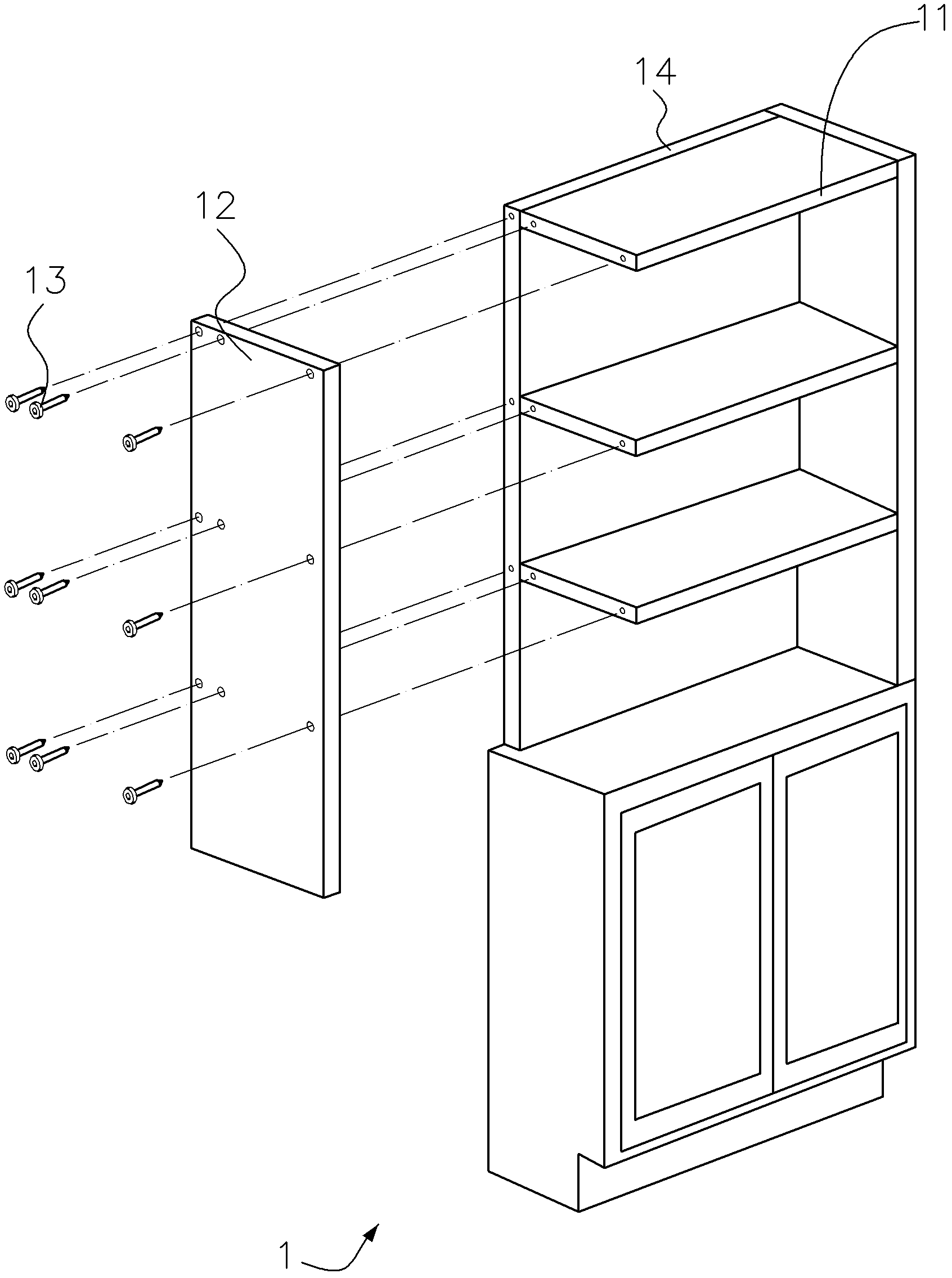
Fastener group structure
A technology of group structure and fasteners, applied in the direction of connecting components, thin plate connections, mechanical equipment, etc., can solve the problems of insufficient mechanical strength, loose cabinet 1, deformation of screw holes, etc., and achieve huge commercial application potential, stability and reliability. the effect of increasing
- Summary
- Abstract
- Description
- Claims
- Application Information
AI Technical Summary
Problems solved by technology
Method used
Image
Examples
no. 1 Embodiment
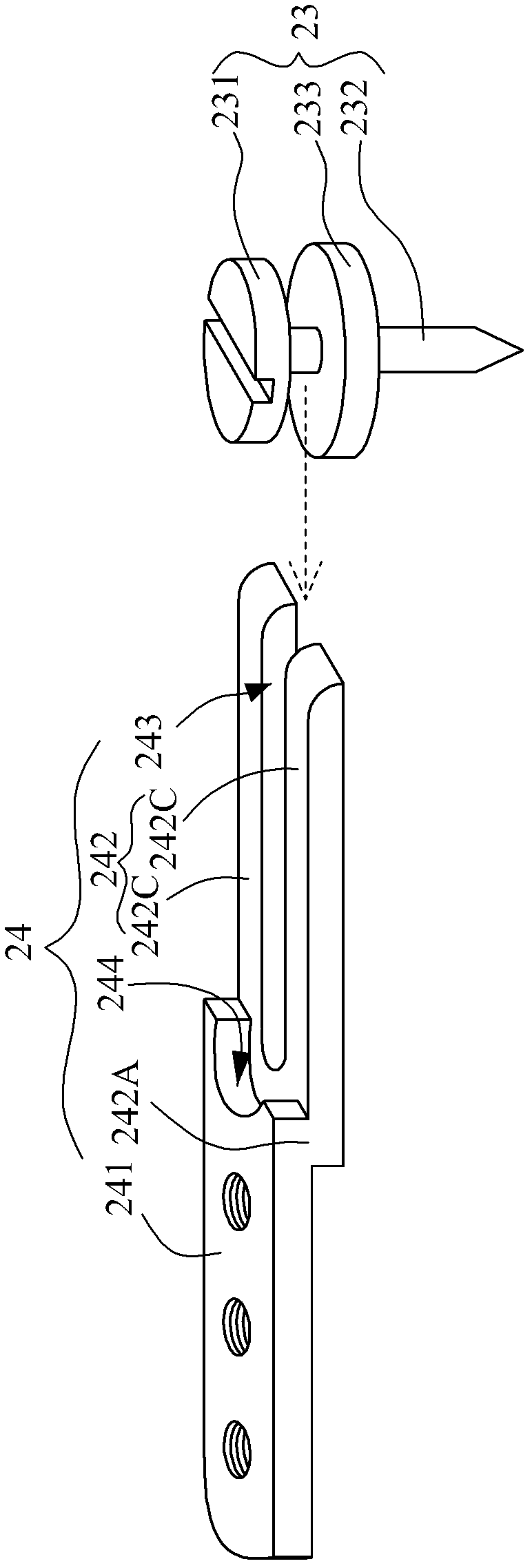
[0045] Such as Figure 2A ~ Figure 2B As shown, a fastener assembly structure is used to connect a first board body 21 and a second board body 22 . The fastener assembly structure includes a pin 24 and a screw 23 , and the screw 23 includes a screw head 231 , a screw rod 232 and a spacer 233 . The screw rod 232 is inserted into the first board body 21 and connected with the first board body 21 . The screw head 231 is spaced apart from the first plate body 21 . The spacer 233 can be abutted against the upper surface 211 of the first board 21 to generate a frictional force in a horizontal direction relative to the first board 21 , thereby increasing the mechanical strength of the combination. In addition, the spacer 233 can also control the depth of the screw 23 drilled into the first plate body 21, so that the screw 23 stops at a specific drilling depth; The position on 232 determines the size of the height H between the screw head 231 and the upper surface 211 , therefore, ...
no. 2 Embodiment
[0049] Such as image 3 As shown, the pin 24 is not provided with the receiving groove 244 , and the screw member 23 is not provided with the spacer 233 . In this embodiment, the screw rod 232 is provided with a threaded structure, and the bottom of the screw rod 232 is a blunt structure. Therefore, before the screw member 23 is drilled into the first plate body 21 , a hole for accommodating the screw rod 232 must be pre-drilled. Moreover, the final position of the screw head 231 (ie the relative height difference between the screw head 231 and the first board body 21 ) is determined by the depth of the pre-drilled hole.
[0050] When the pin 24 and the second board 22 move to the rightmost position, the screw head 231 may or may not abut against the root 242A of the fork-shaped component 242 . When the screw head 231 abuts against the root portion 242A of the fork-shaped element 242 , the screw head 231 can also be in contact with the groove bottom surface 2231 and the fork...
no. 3 Embodiment
[0052] As in the foregoing embodiments, the groove 223 for accommodating the pin 24 is disposed on the lower side of the second board 22; however, as Figure 4 As shown, the groove 223 can also be disposed on the upper side of the first board body 21 for accommodating the screw member 23 . That is to say, the screw rod 232 is fixed on the groove bottom surface 2231 of the first board body 21 , and the pin 24 is firmly fixed on the lower side of the second board body 22 . After the second board 22 and the latch 24 move downward and then rightward, the fork-shaped element 242 and the screw member 23 can be combined with each other.
PUM
 Abstract
Description
Claims
Application Information
 - R&D
- Intellectual Property
- Life Sciences
- Materials
- Tech Scout
- Unparalleled Data Quality
- Higher Quality Content
- 60% Fewer Hallucinations
Browse by: Latest US Patents, China's latest patents, Technical Efficacy Thesaurus, Application Domain, Technology Topic, Popular Technical Reports.
© 2025 PatSnap. All rights reserved.Legal|Privacy policy|Modern Slavery Act Transparency Statement|Sitemap|About US| Contact US: help@patsnap.com


