
Railway box wagon door and railway box wagon

A railway boxcar and door technology, which is applied to railway car body parts, door devices, door/window accessories, etc., can solve the problems of poor sealing of boxcar doors and easily damaged guide rails, so as to improve technical economy, shorten vehicle length, Solve large effects

Active Publication Date: 2012-07-11
CRRC QIQIHAR ROLLING CO LTD
View PDF8 Cites 14 Cited by
  • Summary
  • Abstract
  • Description
  • Claims
  • Application Information

AI Technical Summary

Problems solved by technology

[0006] The invention provides a railway boxcar door, which is used to solve the defects in the prior art that the boxcar door is poorly sealed, the guide rail is easily damaged, and two people need to operate synchronously, so as to improve the integrity and airtightness of the door and realize a single operation by a single person

Method used


Image

  • Railway box wagon door and railway box wagon
  • Railway box wagon door and railway box wagon
  • Railway box wagon door and railway box wagon

Examples


Embodiment 1

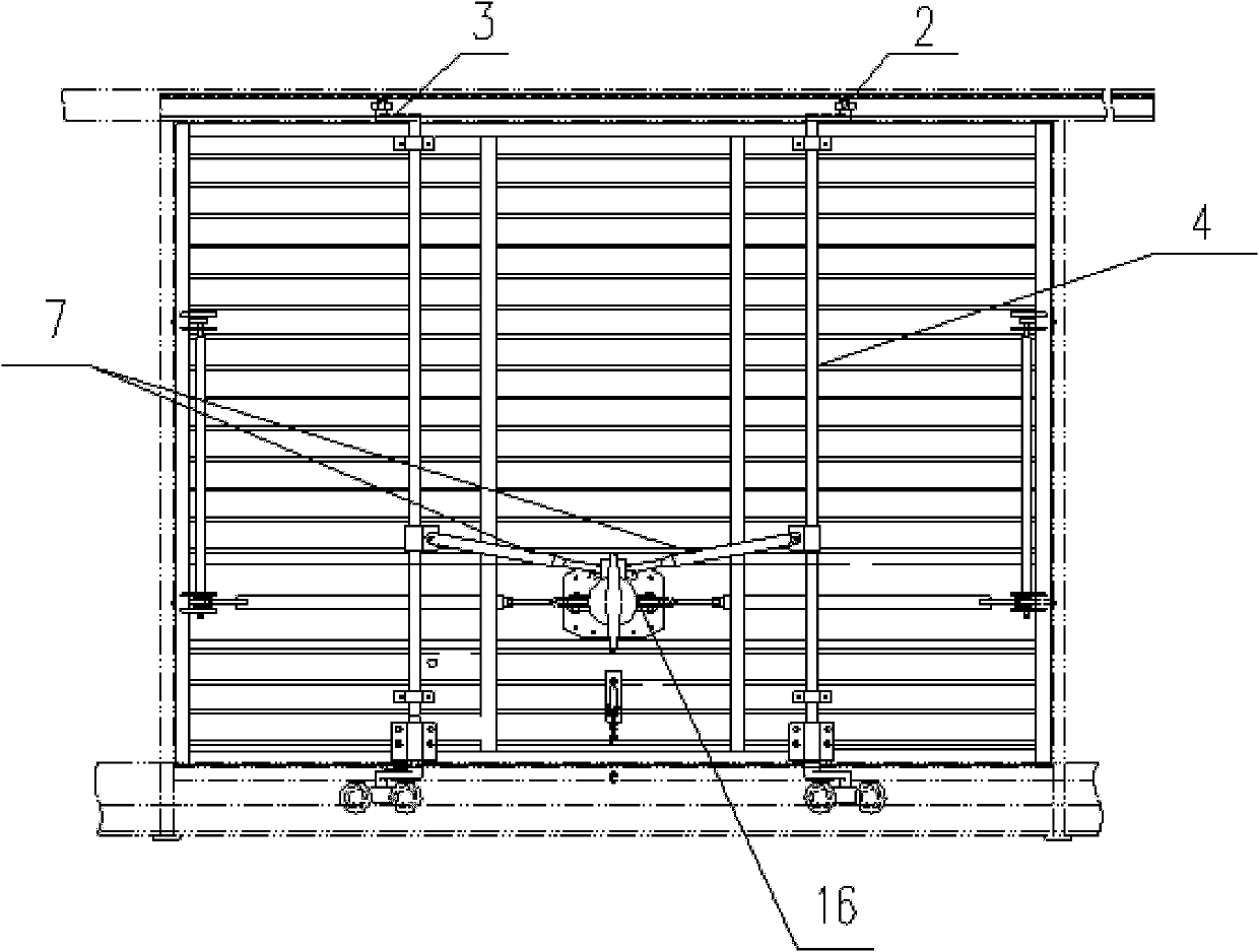
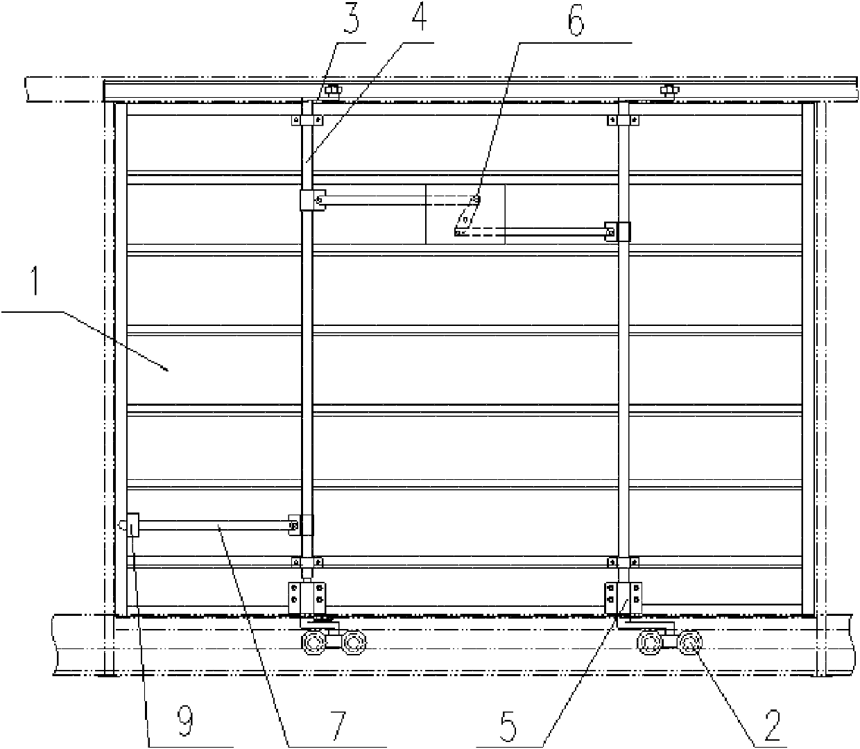
[0041] Figure 3-6 It is a schematic diagram of an embodiment of the present invention, image 3The front view of the closed state of the door of the railway box car provided by Embodiment 1 of the present invention; Figure 4 for image 3 left view of Figure 5 The front view of the opened state of the door of the railway box car provided by Embodiment 1 of the present invention; Figure 6 for Figure 5 left view of .

[0042] As can be seen from the figure, the railway boxcar door includes a door panel 1 and guide rails arranged parallel to the side wall or chassis of the boxcar. The guide rail includes an upper guide rail and a lower guide rail 10. Two groups of rotating shaft units are arranged on the door panel 1, and the rotating shaft unit consists of a shaft seat 5 and a lower rail. The main shaft 4 is composed of a shaft seat 5 fixed on the door panel 1, and the main shaft 4 is penetrated in the shaft seat 5 and is rotatable, so that the rotating shaft unit and t...

Embodiment 2

[0049] Figure 7 The front view of the railway box car door with the middle door provided for the second embodiment of the present invention; the difference from the first embodiment is that a middle door 8 that can be opened and locked from the inside of the car is provided in the middle or appropriate area of ​​the door panel 1. Door 8 can be opened and locked in the car, which is convenient for escorts in the car to get in and out when the door is closed. The form and position of middle door 8 can be adjusted according to user requirements.

Embodiment 3

[0051] Figure 9 It is a cross-sectional view of the lower guide rail of the door of a railway box car provided by Embodiment 3 of the present invention.

[0052] The structure of the boxcar door is the same as that of the first embodiment, the difference is that the lower guide rail 10 in the third embodiment is fixed on the side wall of the boxcar through the support block 17, and the lower surface of the end of the support block 17 near the lower guide rail 10 is higher than that of the boxcar. The lower surface at one end; the lower end of the lower guide rail 10 and the side away from the box car is covered with a guard plate, which can prevent the forklift driver from inaccurately judging the distance, and the fork fork 15 of the forklift scrapes on the lower guide rail while increasing the overall rigidity of the guide rail. The lower end will cause the lower guide rail to tip over and deform, which will affect the sliding of the door and even cause the door to drop in ...


PUM


Abstract

The invention discloses a railway box wagon door and a railway box wagon. The railway box wagon door comprises a door plank and guide rails, wherein the guide rails are arranged on the side wall or bottom frame of the box wagon in parallel; the door plank is rotatably provided with two groups of rotating shaft units; each rotating shaft unit is composed of a shaft seat and a main shaft; the shaft seats are fixed on the door plank; the main shafts are arranged in the shaft seats in a penetrating manner and can rotate; two ends of the main shaft in each group of rotating shaft unit are both provided with crank throws; a pulley is fixed on the other end of each crank throw; the pulleys are arranged in the guide rails and are guided to slide in the guide rails; a handle which can drive the main shaft to rotate and operate is fixed on the main shaft in one group of spindle unit; and a synchronous door-opening connecting rod mechanism which causes the two main shafts to synchronously rotate is arranged between the main shafts of the two groups of spindle units. The railway box wagon door has the advantages of being simple, reasonable and compact in structure, overcoming various defects in the prior art, improving the integrity and tightness of the wagon door, and realizing the purpose of operating by single person in one time.

Description

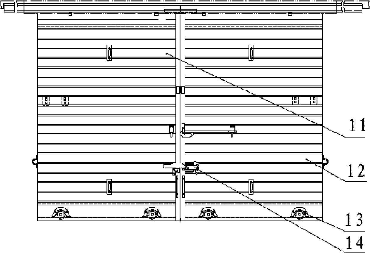
technical field [0001] The invention relates to railway transport vehicle technology, in particular to a railway boxcar door and a railway boxcar. Background technique [0002] In order to meet the requirements of cargo loading and unloading and forklift entry and exit, the railway box car is equipped with side doors on the side walls on both sides. [0003] figure 1 It is a structural schematic diagram of a sliding sliding door of an existing railway box car. The car door has two door panels: a left door 11 and a right door 12. A door locking device 14 is arranged in the middle of the two door panels. This kind of car door has the following disadvantages: the structure of the two car doors is loose, and the sealing performance is poor; And the locking device of this car door structure is located at the outside of the car, which is not convenient for the operation of the escort personnel in the car and getting in and out during temporary parking. [0004] In addition, at...

Claims


Application Information

Patent Timeline
Patent Type & Authority Applications(China)
IPC IPC(8): E06B3/46E05D13/00B61D19/00
Inventor 贺茂盛贾志学田海增李志刚岳林汉于雷杨爽李涛
Owner CRRC QIQIHAR ROLLING CO LTD
Learn More