Combined steel-plastic composite lacing bar

A composite tie rod and combined technology, applied in the field of building materials, can solve the problems of poor bending resistance and shear resistance, and achieve the effects of small tensile deformation, enhanced pullout resistance, and high construction efficiency.

Inactive Publication Date: 2012-07-11
YANSHAN UNIV
View PDF5 Cites 0 Cited by
  • Summary
  • Abstract
  • Description
  • Claims
  • Application Information

AI Technical Summary

Problems solved by technology

Most of the existing composite material ties are steel-plastic composite ties, which are mainly composed of high-strength zinc-coated steel wires wrapped with polyethylene resin. Both the tensile and deformation properties have been significantly improved, but its bending and shearing properties are still poor. Therefore, it is necessary to prevent half-folding during transportation and storage, and not to contact with hard angular fillers directly.

Method used


Image

  • Combined steel-plastic composite lacing bar
  • Combined steel-plastic composite lacing bar
  • Combined steel-plastic composite lacing bar

Examples


Embodiment Construction

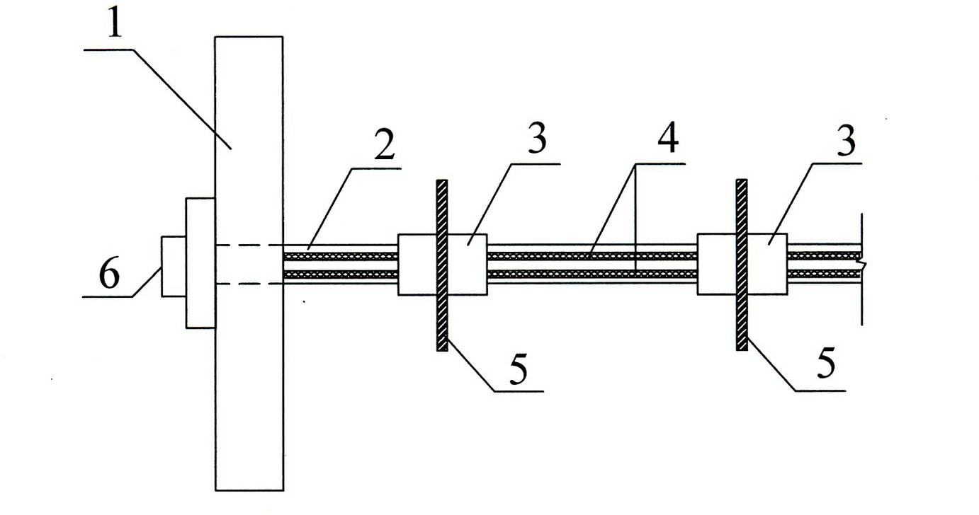
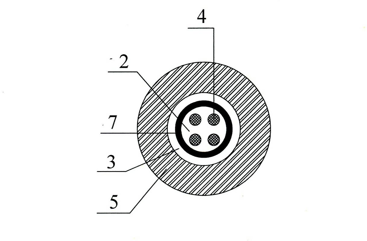
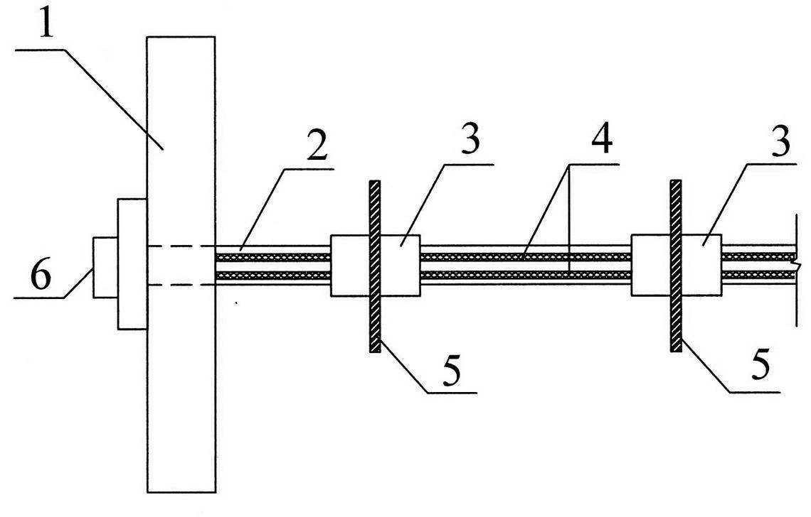
[0016] exist figure 1 and figure 2 In the schematic diagram of the cross-section of a combined steel-plastic composite lacing rod shown, four 10mm steel strands 4 are tightly wrapped with a geosynthetic casing 2 with a wall thickness of 5mm to form the main body of the lacing rod. The outer surface of the above-mentioned geosynthetic casing is engraved with concave-convex grooves, and on the above-mentioned lacing bar, a steel ring stopper 5 with an outer diameter of 90mm is provided every 1m. A steel extrusion sleeve 3 with a thickness of 10 cm and a wall thickness of 4 mm is fixed. The above-mentioned ring baffle and the extrusion sleeve pass through the geosynthetic casing, and the space between the extrusion sleeve and the above-mentioned geosynthetic casing is filled with The rubber glue 7 is used to connect one end of the lacing bar to the wall panel 1 with the anchor head 6.


PUM

PropertyMeasurementUnit
Diameteraaaaaaaaaa
Wall thicknessaaaaaaaaaa
Outer diameteraaaaaaaaaa

Abstract

The invention discloses a combined steel-plastic composite lacing bar. The main structure of the combined steel-plastic composite lacing bar is as follows: a geosynthetics sleeve is tightly wrapped outside 3-10 steel strands with the diameter of 10-15mm to form a lacing bar main body, wherein the wall thickness of the sleeve is 5-15mm; a concave-convex groove is engraved on the outer surface of the geosynthetics sleeve; steel ring separation blades with the external diameter of 80-200mm are arranged at the intervals of 1-5m on the lacing bar; the two sides of the steel ring separation blade are fixed by a steel extrusion sleeve, wherein the length of the steel extrusion sleeve is 5-15cm and the wall thickness of the steel extrusion sleeve is 2-5mm; the ring separation blade and the extrusion sleeve penetrate through the geosynthetics sleeve; and anti-friction padding is filled between the extrusion sleeve and the geosynthetics sleeve. The combined steel-plastic composite lacing bar disclosed by the invention has low construction cost, simple and convenient mode of connection, high efficiency of construction, excellent compression resistance, tensile strength, shear resistance and the like, good resistance to corrosion and small tensile deformation, and can prevent a wall panel from drum deformation.

Description

technical field [0001] The invention belongs to the field of building materials, in particular to a tie bar for reinforcing retaining walls. Background technique [0002] Reinforced retaining wall belongs to light retaining structure. Due to its advantages of low cost, simple construction, small footprint, short construction period and beautiful appearance, it is widely used in domestic highways, railways, coal mines and water conservancy departments. [0003] Reinforced soil retaining wall is a composite structure composed of three parts: wall panels, tie bars, and fillers. Relying on the friction between fillers and tie bars, the earth pressure on the wall panels (that is, the strength of reinforced earth retaining walls) is balanced. internal stability), and use this composite structure to resist the earth pressure generated by the filler at the end of the ties (that is, the external stability of the reinforced soil retaining wall), thus ensuring the stability of the enti...

Claims


Application Information

Patent Timeline
IPC IPC(8): E02D29/02
Inventor 曹海莹
Owner YANSHAN UNIV
Why Eureka
Try Eureka