A substrate carrying device and substrate processing equipment using the device

A substrate carrying and substrate technology, applied in the direction of chemically reactive gas, gaseous chemical plating, crystal growth, etc., can solve the problem of increased difficulty in the design and control of airflow field and temperature field, stability and uniformity of epitaxy process Unfavorable effects, difficulty in pallet processing and increased processing costs, etc., to achieve the effect of ensuring process stability and uniformity, ensuring stability and uniformity, and reducing production costs

Active Publication Date: 2016-03-30
BEIJING NAURA MICROELECTRONICS EQUIP CO LTD
View PDF8 Cites 0 Cited by
  • Summary
  • Abstract
  • Description
  • Claims
  • Application Information

AI Technical Summary

Problems solved by technology

[0006] First of all, on the basis of the structure of the above-mentioned substrate carrying device, if the production capacity of the equipment is to be further increased, it can only be realized by increasing the size of the above-mentioned large tray to carry more substrates; As far as pallets made of materials are concerned, if the size is to be further increased on the existing basis, it will inevitably lead to a sharp increase in the processing difficulty and processing cost of the pallet, which will result in an increase in equipment costs and operating costs
[0007] Moreover, after the size of the large tray increases, it will also increase the difficulty of designing and controlling the airflow field and temperature field during the process, which will bring adverse effects on the control of parameters such as stability and uniformity of the epitaxial process.
In the end, enterprises will face the dilemma of equipment cost and process quality
[0008] Moreover, during the process, the process gas enters the chamber from the gas supply device of the process chamber and fills the entire chamber space, thereby forming the required film layer on the surface of the substrate; Carry the substrate, therefore, the process gas flowing through the other side of the tray is directly discharged from the process chamber as waste gas, resulting in a serious waste of process gas, which in turn increases unnecessary production costs virtually

Method used


Image

  • A substrate carrying device and substrate processing equipment using the device
  • A substrate carrying device and substrate processing equipment using the device
  • A substrate carrying device and substrate processing equipment using the device

Examples


Embodiment Construction

[0041] In order for those skilled in the art to better understand the technical solution of the present invention, the substrate carrying device provided by the present invention and the substrate processing equipment using the substrate carrying device will be described in detail below with reference to the accompanying drawings.

[0042]The substrate carrying device provided by the present invention is used to carry the substrate in the substrate processing equipment, the substrate carrying device includes at least one tray, and each tray has two opposite disk surfaces for carrying the substrate; That is to say, both sides of each tray can be used to carry substrates, so that compared with a substrate carrying device of the same size, it can carry more substrates at one time; therefore, the substrate carrying device has a stronger Carrying capacity, when applied to process equipment, can effectively improve the production capacity of process equipment.

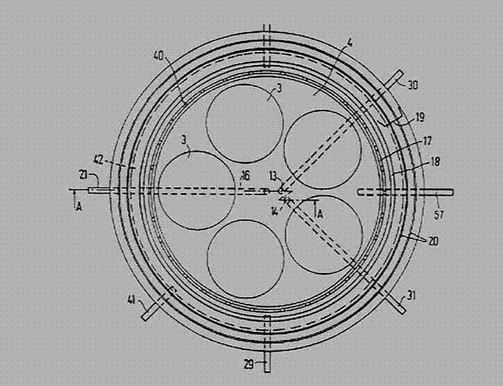
[0043] see image 3...


PUM


Abstract

Disclosed is a substrate bearing apparatus for bearing substrates, comprising at least one tray (71, 72, 73), wherein each tray (71, 72, 73) has two opposite tray surfaces for bearing substrates. Compared with current common substrate bearing apparatus of the same size, the substrate bearing apparatus can bear more substrate during processes, thus effectively increasing device production capacity and process gas utilization rate. Also disclosed is a substrate processing device using the substrate bearing apparatus.

Description

technical field [0001] The invention relates to the technical field of microelectronic production, in particular to a substrate carrying device and substrate processing equipment using the substrate carrying device. Background technique [0002] In the field of microelectronics product manufacturing, Metal Organic Chemical Vapor Deposition technology (MetalOrganicChemicalVaporDeposition, hereinafter referred to as MOCVD) is a main method for growing thin-layer single crystals of III-V, II-VI compounds and alloys. It has the advantages of precise control of component layer thickness interface, low maintenance cost, and easy large-scale production. Therefore, this technology is widely used in the production process of optoelectronic materials such as gallium arsenide, indium phosphide, and gallium nitride. [0003] see figure 1 , is a system schematic diagram of an MOCVD device. The equipment usually includes several major components such as a process chamber, a gas supply ...

Claims


Application Information

Patent Timeline
Patent Type & Authority Patents(China)
IPC IPC(8): C30B25/12
CPCH01L21/68771C23C16/4583
Inventor 徐亚伟张秀川
Owner BEIJING NAURA MICROELECTRONICS EQUIP CO LTD
Why Eureka
Try Eureka