
Automatic feeder of surface grinder

An automatic feeding, surface grinding machine technology, applied in the direction of grinding drive devices, grinding machine parts, grinding/polishing equipment, etc., can solve the problems of low reliability, large noise and vibration, commutation failure, etc. Guaranteed smoothness and accuracy, noise and vibration suppression, vibration and noise suppression effect

Inactive Publication Date: 2012-07-11
史玉福
View PDF5 Cites 4 Cited by
  • Summary
  • Abstract
  • Description
  • Claims
  • Application Information

AI Technical Summary

Problems solved by technology

One is to use a hydraulic system, which has a complex structure and high cost. The cost of each set is about 20,000 yuan, but its performance is stable and high reliability; the other is to use a motor plus a mechanical commutator (referred to as the electric system) , the motor can only run in one direction. When the workbench moves forward, the motor drives the forward gear to work. When it moves in the reverse direction, the electromagnetic clutch switches to the reverse gear to work, so as to drive the workbench to realize automatic reciprocation from left to right. Although this method is relatively simple in structure , the cost is also very low, but the noise and vibration are large when the gear is switched, and the life of the gear is very short. Due to the vibration, the machining accuracy of the workpiece cannot meet the requirements or even be scrapped, and the commutation often fails due to the failure of the electromagnetic clutch, and the reliability is low. , poor performance and low penetration rate; as a result, the current small flat grinding can only be operated manually due to cost reasons, and only the hydraulic system is used on large flat grinding

Method used


Image

  • Automatic feeder of surface grinder
  • Automatic feeder of surface grinder

Examples


Embodiment Construction

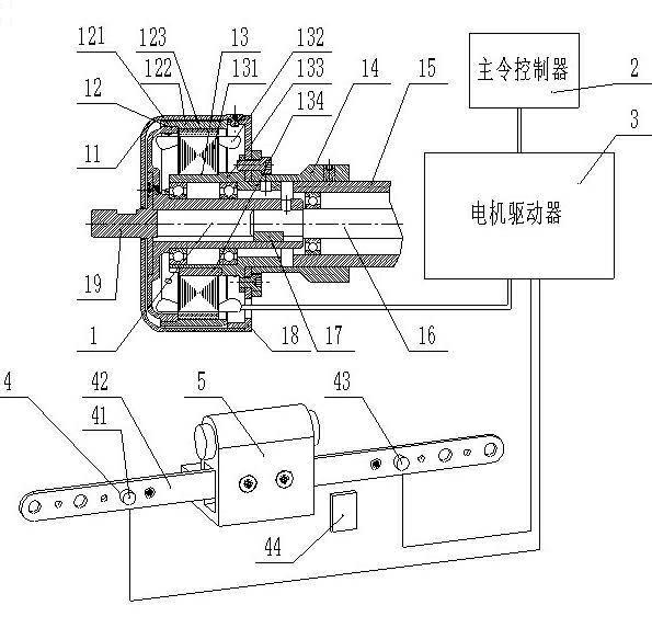
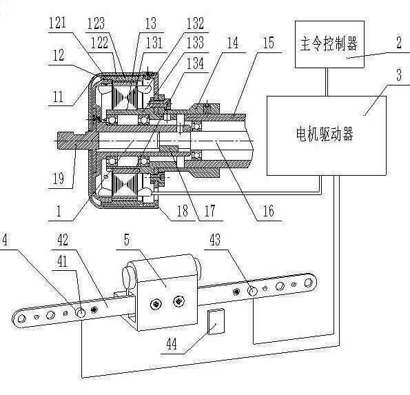
[0016] From figure 1 It can be seen from the figure that an automatic feeder for a surface grinder is composed of a brushless DC motor 1, a master controller 2, a motor driver 3 and a stroke module 4, and the motor driver 3 is connected to the motor 1 and the master through cables. The controller 2 and the stroke module 4 are connected.

[0017] The brushless DC motor 1 is fixed on the drive shaft sleeve 15 of the grinder, and the inner sleeve of the cup-shaped rotor 12 is directly sleeved on the drive shaft 16 and connected by a flat key 17 . The brushless DC motor 1 includes an organic casing 11 , a cup-shaped rotor 12 , a stator 13 , a connecting sleeve 14 , a front cover 18 , and an external shaft 21 . The stator 13 is composed of a stator core 131, a three-phase stator winding and a sensor 132, a stator cover 133 and a flat key 134, and a three-phase stator winding and a position sensor 132 are placed in the slot of the stator core 131. The inner ring is connected with ...


PUM


Abstract

The invention relates to an automatic feeder of a surface grinder, which comprises a brushless direct-current motor, a master controller, a motor driver and a travel module. The brushless direct-current motor consists of a stator, a cup-shaped rotor, a front edge cover, a shell and an outer connecting shaft, the stator is fixed onto a shaft sleeve of a driving shaft of the grinder, a shaft sleeve of an inner ring of the cup-shaped rotor is directly sleeved on the driving shaft of a worktable of the grinder in a key joint manner, action instructions are emitted by the master controller and are processed by a microcomputer chip in the motor driver, and accordingly the brushless direct-current motor connected with a driving circuit is driven to start and stop by the driving circuit; and two travel switches of the travel model control shift motion of the worktable, directions are automatically changed when the travel switches act, and accordingly automatic feeding of the surface grinder is realized. The automatic feeder of the surface grinder is simple in structure, long in service life, convenient in installation and flexible, simple and convenient in operation, and is safe and reliable.

Description

technical field [0001] The invention belongs to mechanical processing auxiliary equipment, in particular to an automatic feeder for a surface grinder that drives a surface grinder workbench to realize automatic reciprocation from left to right. Background technique [0002] At present, there are two ways to realize the automatic reciprocating device of the workbench on the surface grinder on the market. One is to use a hydraulic system, which has a complex structure and high cost. The cost of each set is about 20,000 yuan, but its performance is stable and high reliability; the other is to use a motor plus a mechanical commutator (referred to as the electric system) , the motor can only run in one direction. When the workbench moves forward, the motor drives the forward gear to work. When it moves in the reverse direction, the electromagnetic clutch switches to the reverse gear to work, so as to drive the workbench to realize automatic reciprocation from left to right. Altho...

Claims


Application Information

Patent Timeline
IPC IPC(8): B24B47/20
Inventor 史玉福
Owner 史玉福
Learn More