Gantry-travelling drive mechanism

A technology of driving mechanism and gantry, which is applied in the direction of metal processing machinery parts, metal processing equipment, manufacturing tools, etc., can solve the problem of insufficient rolling moment of the reducer, and achieve the effect of easy assembly, high transmission precision and simple structure

Inactive Publication Date: 2012-07-11
SANY GRP
View PDF8 Cites 1 Cited by
  • Summary
  • Abstract
  • Description
  • Claims
  • Application Information

AI Technical Summary

Problems solved by technology

[0006] The purpose of the present invention is to solve the problem of insufficient rolling moment of the reducer in the prior art, and improve the precision, rigidity and reliability of the X-axis transmission

Method used


Image

  • Gantry-travelling drive mechanism
  • Gantry-travelling drive mechanism
  • Gantry-travelling drive mechanism

Examples


Embodiment Construction

[0024] The present invention will be further described in detail below in conjunction with the drawings and specific embodiments. The specific embodiments described here are only used to explain the present invention, and not used to limit the protection scope of the present invention.

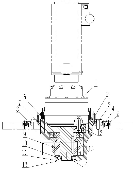
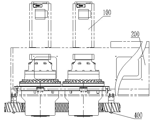
[0025] Combined reference figure 1 with figure 2 , In the gantry moving drive mechanism of the present invention, two servo motors 100 are each connected to a deceleration mechanism (see figure 2 ), each deceleration mechanism includes:

[0026] The transition support sleeve 2 fixed on the sliding seat 200 has one end sealed and the other end open;

[0027] Reducer 1, one end is connected to the servo motor 100, and the other end is connected to a transition shaft 6, the transition shaft 6 is arranged in the transition support sleeve 2;

[0028] Gear 9 is fixed on the transition shaft 6;

[0029] A number of cylindrical roller bearings 10 are arranged between the gear 9 and the transition suppo...


PUM


Abstract

The invention provides a gantry-travelling drive mechanism which is characterized in that two servo motors are respectively connected with a decelerating mechanism, and each decelerating mechanism comprises a transition supporting sleeve, a decelerating device, a gear and a plurality of cylindrical roller bearings, wherein the transition supporting sleeve is fixed on a sliding seat, one end of the transition supporting sleeve is sealed, and the other end of the transition supporting sleeve is opened; one end of the decelerating device is connected with the servo motor, the other end of the decelerating device is connected with a transition shaft, and the transition shaft is arranged in the transition supporting sleeve; the gear is fixed on the transition shaft; and the plurality of cylindrical roller bearings are arranged between the gear and the transition supporting sleeve. The gantry-travelling drive mechanism provided by the invention has the advantages that: 1) the transmission accuracy is high; as a key block is added, the transmission stability and the transmission reliability are ensured; and the transition supporting sleeve and the transition shaft can be manufactured independently, therefore, the cost is low, and no special decelerating device is required to be bought; 2) the gantry-travelling drive mechanism is simple in structure and easy to assemble; and 3) due to the eliminating of backlash of the two motors, the low-speed and high-accuracy operation without transmission backlash errors of the gantry-travelling drive mechanism is ensured.

Description

Technical field [0001] The invention relates to a driving mechanism, in particular to a gantry moving driving mechanism. Background technique [0002] Moving beam moving column gantry boring and milling machine, mainly composed of bed, sliding seat, worktable, left and right columns, beams, slides, rams, headstock and other main components, fixed bed worktable, gantry frame along the bed guide rail Horizontal movement, the beam moves vertically along the column guide rail, the ram-type spindle head can move horizontally along the slide rail on the beam guide rail, or vertically along the slide guide rail, suitable for cutting large, medium-sized and heavy metal planes and holes Machining is widely used in rough and fine machining of heavy and large complex parts in various industries. [0003] The movable beam movable column gantry boring and milling machine can also process the holes in the cavity of the part and the plane in the narrow space, and has the functions of milling, bo...

Claims


Application Information

Patent Timeline
Patent Type & Authority Applications(China)
IPC IPC(8): B23Q5/36
Inventor 潘威孟祥东廖建雄
Owner SANY GRP
Why Eureka
Try Eureka