
Hydrocarbon synthesis reaction apparatus, hydrocarbon synthesis reaction system, and hydrocarbon synthesis reaction method

一种反应装置、烃合成的技术,应用在烃合成反应装置领域,能够解决催化剂劣化、烃合成成品率下降、催化剂粒子堵塞等问题,达到抑制劣化、提高成品率的效果

Active Publication Date: 2012-07-04
JAPAN OIL GAS & METALS NAT CORP +5
View PDF2 Cites 3 Cited by
  • Summary
  • Abstract
  • Description
  • Claims
  • Application Information

AI Technical Summary

Problems solved by technology

[0007] First, since the FT synthesis reaction continues due to the synthesis gas remaining in the reaction vessel, the reaction heat accompanying the exothermic reaction cannot be effectively removed due to the deterioration of the fluidity of the catalyst slurry, and a hot spot is temporarily formed in the catalyst slurry, which may Part of the catalyst deteriorates due to excessive temperature rise
At this time, after restarting the operation of restarting the supply of the synthesis gas from the synthesis gas supply mechanism, there is a problem that the yield of hydrocarbon synthesis by the FT synthesis reaction is lower than before the operation of stopping the supply of the synthesis gas is stopped.
[0008] In addition, catalyst particles may clog the synthesis gas supply path
At this time, after the operation is restarted, the synthesis gas from the synthesis gas supply mechanism cannot be smoothly supplied into the reaction vessel, and in the worst case, there is a problem that the synthesis gas cannot be supplied at all.

Method used


Image

  • Hydrocarbon synthesis reaction apparatus, hydrocarbon synthesis reaction system, and hydrocarbon synthesis reaction method
  • Hydrocarbon synthesis reaction apparatus, hydrocarbon synthesis reaction system, and hydrocarbon synthesis reaction method
  • Hydrocarbon synthesis reaction apparatus, hydrocarbon synthesis reaction system, and hydrocarbon synthesis reaction method

Examples


Embodiment Construction

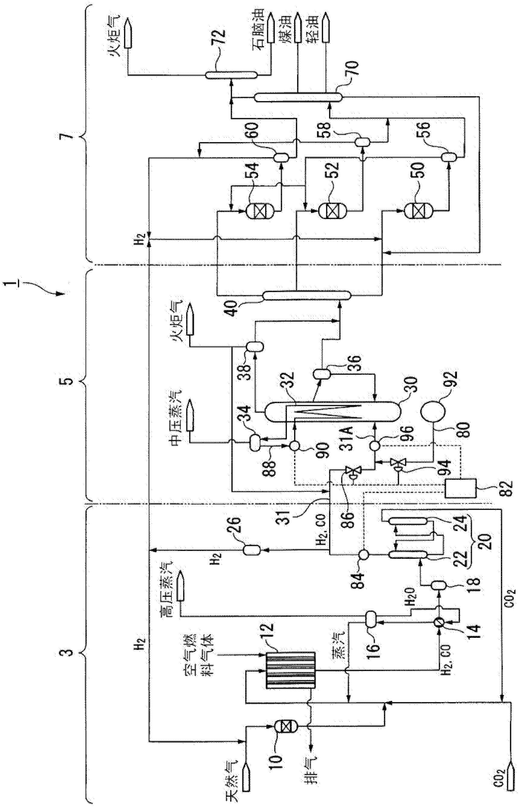
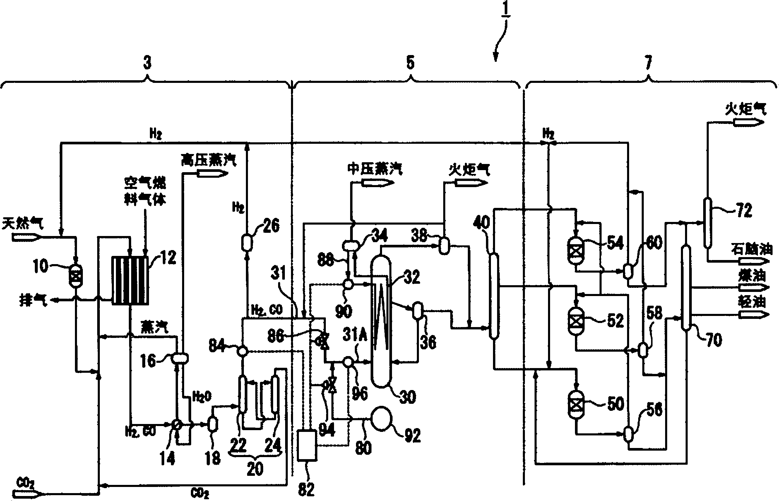
[0040] Below, refer to figure 1 A liquid fuel synthesis system according to an embodiment of the present invention will be described.

[0041] like figure 1 As shown, a liquid fuel synthesis system (hydrocarbon synthesis reaction system) 1 is a factory facility for performing a GTL process for converting hydrocarbon raw materials such as natural gas into liquid fuels. This liquid fuel synthesis system 1 is composed of a synthesis gas generation unit 3 , an FT synthesis unit (hydrocarbon synthesis reaction device) 5 , and a product refining unit 7 . The synthesis gas generation unit 3 is used to reform natural gas as a hydrocarbon feedstock to generate synthesis gas containing carbon monoxide gas and hydrogen gas. The FT synthesis unit 5 generates liquid hydrocarbons from the generated synthesis gas by using the FT synthesis reaction. The product refining unit 7 hydrogenates and fractionates liquid hydrocarbons produced by the FT synthesis reaction to produce base materials ...


PUM


Abstract

Discloses is a hydrocarbon synthesis reaction apparatus which comprises a reaction vessel and a synthetic gas supply passage through which a synthetic gas is supplied to the reaction vessel, and which can synthesize a hydrocarbon upon the contact of the synthetic gas with a catalyst slurry in the reaction vessel. The apparatus additionally comprises a standby supply passage and a fluid-heating means, wherein the standby supply passage can supply an inert gas or a hydrogen gas to the reaction vessel through the synthetic gas supply passage when the standby supply passage is connected to the synthetic gas supply passage and the supply of the synthetic gas from the synthetic gas supply means to the synthetic gas supply passage is stopped, and the fluid-heating means can heat either one of a fluid that passes through a flow path that is located in the synthetic gas supply passage and is closer to the reaction vessel than a connection with the standby supply passage or a fluid that passes through the standby supply passage.

Description

technical field [0001] The invention relates to a hydrocarbon synthesis reaction device, a hydrocarbon synthesis reaction system and a hydrocarbon synthesis reaction method. [0002] This application claims priority based on Japanese Patent Application No. 2009-200346 for which it applied in Japan on August 31, 2009, and uses the content here. Background technique [0003] In recent years, GTL (Gas To Liquids: liquid fuel synthesis) technology has been developed as one of methods for synthesizing liquid fuels from natural gas. In GTL technology, natural gas is reformed to produce carbon monoxide gas (CO) and hydrogen (H 2 ) as the main component of synthesis gas, using the synthesis gas as a raw material gas and using a Fischer-Tropsch synthesis reaction (hereinafter referred to as "FT synthesis reaction") to synthesize hydrocarbons using a catalyst, and then hydrogenating and refining the hydrocarbons to produce petroleum gas. Naphtha (gasoline), kerosene, light oil, wax ...

Claims


Application Information

Patent Timeline
Patent Type & Authority Applications(China)
IPC IPC(8): C10G2/00C10G45/00
CPCC10G2/342B01J8/1827B01J8/1809C10G2300/4031
Inventor 大西康博加藤让山田荣一
Owner JAPAN OIL GAS & METALS NAT CORP
Learn More