
Miniaturized S waveband micro-strip ferrite circulator

A ferrite and circulator technology, applied in the microwave field, can solve the problems of difficult adjustment of device frequency characteristics, lack of flexibility in impedance matching, large overall size, etc., and achieve the effect of compact structure, convenient design, and reduced overall length

Inactive Publication Date: 2012-07-04
彭龙
View PDF1 Cites 8 Cited by
  • Summary
  • Abstract
  • Description
  • Claims
  • Application Information

AI Technical Summary

Problems solved by technology

The central conductor junction of the circulator and the microstrip transmission line coupled and matched with it are located on the same ferrite substrate, which lacks flexibility in the design of impedance matching; single Y junction or double Y junction structure is used for coupling and matching, Limited by the relative permittivity of the ferrite substrate, the overall size is large; the structure design is relatively simple, and the frequency characteristics of the device are not easy to adjust

Method used


Image

  • Miniaturized S waveband micro-strip ferrite circulator
  • Miniaturized S waveband micro-strip ferrite circulator
  • Miniaturized S waveband micro-strip ferrite circulator

Examples


Embodiment approach

[0017] The present invention will be described in further detail below in conjunction with the accompanying drawings and an embodiment, and it cannot be assumed that the embodiment of the present invention is limited thereto.

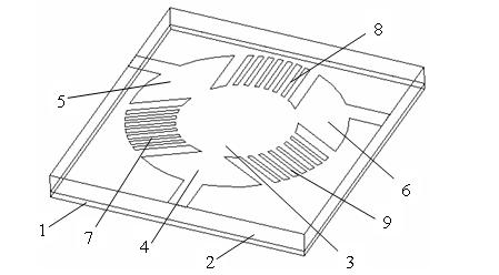
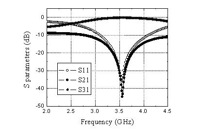
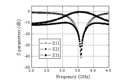
[0018] Such as Figure 3 to Figure 5 As shown, the embodiment of the present invention provides a miniaturized S-band microstrip ferrite circulator with a working center frequency of 3.55 GHz and a bandwidth of 200 MHz. The reflection and isolation at the center frequency are better than 35 dB, and the insertion loss is lower than 0.5 dB. , the standing wave ratio is less than 1.1. The circulator is manufactured using the currently mature microstrip film technology.

[0019] Such as figure 1 and figure 2 As shown, the present invention provides a miniaturized S-band microstrip ferrite circulator.

[0020] The saturation magnetization of the spun ferrite substrate 2 is 600Gs, the relative permittivity is 13.3, and the loss tangent is 2×10 -4 , and ...


PUM

PropertyMeasurementUnit
Thicknessaaaaaaaaaa

Abstract

The invention discloses a miniaturized S waveband micro-strip ferrite circulator, belonging to the field of a ferrite device in a microwave technology. The circulator comprises a metal ground layer, a gyromagnetic ferrite substrate, a center junction, three large Y-shaped arms and three small Y-shaped arms. The three large Y-shaped arms and the three small Y-shaped arms are sequentially separated at intervals, and the three large Y-shaped arms and the three small Y-shaped arms respectively take a circle center of the center junction as a symmetric center to be distributed on the upper surface of the gyromagnetic ferrite substrate in a manner of forming included angles of 120 degrees among the three large Y-shaped arms and the three small Y-shaped arms. Each large Y-shaped arm is composed of two sections of micro-strip branches with different resistances and the micro-strip branch which is far away from the center junction can be connected with an external port to carry out fed. Each small Y-shaped arm is composed of a plurality of strips in parallel and the quantity of the strips can be adjusted. According to the invention, a novel double-Y junction structure is utilized for designing so that structure disadvantages and design disadvantages of the existing micro-strip ferrite circulator are broken through, the resistance matching is improved and the frequency property is easy to adjust; and the miniaturized S waveband micro-strip ferrite circulator has the advantages of compact structure, reduced whole size and improved integration level, thereby meeting miniaturized requirements of the micro-strip circulator.

Description

technical field [0001] The invention belongs to the field of microwave technology, and relates to a miniaturized S-band microstrip ferrite circulator. Background technique [0002] Ferrite circulator is a multi-port microwave passive device, in which electromagnetic waves are transmitted in a certain circular direction, and the opposite direction is isolated. It is an indispensable special device in the fields of aviation, spaceflight, and communication. In systems and equipment such as ground radar, airborne and missile-borne radar, electronic warfare, air defense missile weapons, and mobile communication base stations, ferrite circulators can be used as independent units of hybrid integrated circuits, which play a double role and improve the system The role of matching. Due to the advantages of miniaturization, light weight, low production cost, short production cycle, high reliability and good performance, the microstrip ferrite circulator better adapts to the developmen...

Claims


Application Information

Patent Timeline
IPC IPC(8): H01P1/387H01P11/00
Inventor 彭龙朱兴华
Owner 彭龙
Learn More